EasyManuals Logo

Siemens SINAMICS Series User Manual

Siemens SINAMICS Series
758 pages
To Next Page IconTo Next Page
To Previous Page IconTo Previous Page
Page #247 background imageLoading...
Page #247 background image
Additional system components
7.5 Terminal Module TM31
SINAMICS DCM DC Converter
Operating Instructions, 12/2018, A5E34763375A
245
WARNING
Electric shock in the event of voltage flashovers at the temperature sensor
Voltage flashovers in the signal electronics can occur in motors without safe electrical
separation of the temperature sensors.
• Use temperature sensors that comply with the specifications relating to protective
separation.
7.5.3.8
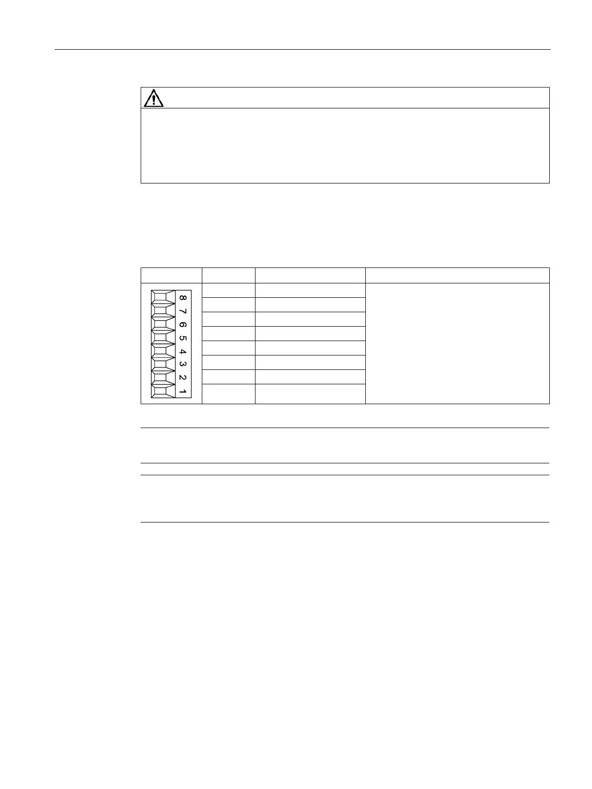
X540 auxiliary voltage for the digital inputs
Table 7- 39 Screw terminal X540
Connector
Terminal
Designation
Technical specifications
8
+24 V
Voltage: +24 V DC
Max. total load current of +24 V auxiliary
voltage for terminals X540 and X541
combined: 150 mA
7
+24 V
6
+24 V
5
+24 V
4
+24 V
3
+24 V
2
+24 V
1 +24 V
Note
This power supply is only used for powering the digital inputs.
Note
If the 24 V supply is briefly interrupted, the auxiliary voltage for the digital inputs is
deactivated for this time.

Table of Contents

Other manuals for Siemens SINAMICS Series

Questions and Answers:

Question and Answer IconNeed help?

Do you have a question about the Siemens SINAMICS Series and is the answer not in the manual?

Siemens SINAMICS Series Specifications

General IconGeneral
Product LineSINAMICS
Cooling MethodAir-cooled, Liquid-cooled
Voltage Range200 V to 690 V
Power Range0.12kW - 250kW
Communication InterfacesPROFINET, PROFIBUS, Ethernet
Control ModesVector control, V/f control
Protection ClassIP20
TypeVariable Frequency Drives (VFD)

Related product manuals