Description
1.4 Coordinate systems
Cylindrical grinding
20 Programming and Operating Manual, 07/2009, 6FC5398-4CP10-2BA0
The origin of this coordinate system is the machine zero.
This point is only a reference point which is defined by the machine manufacturer. It does not
have to be approachable.
The traversing range of the machine axes can by in the negative range.
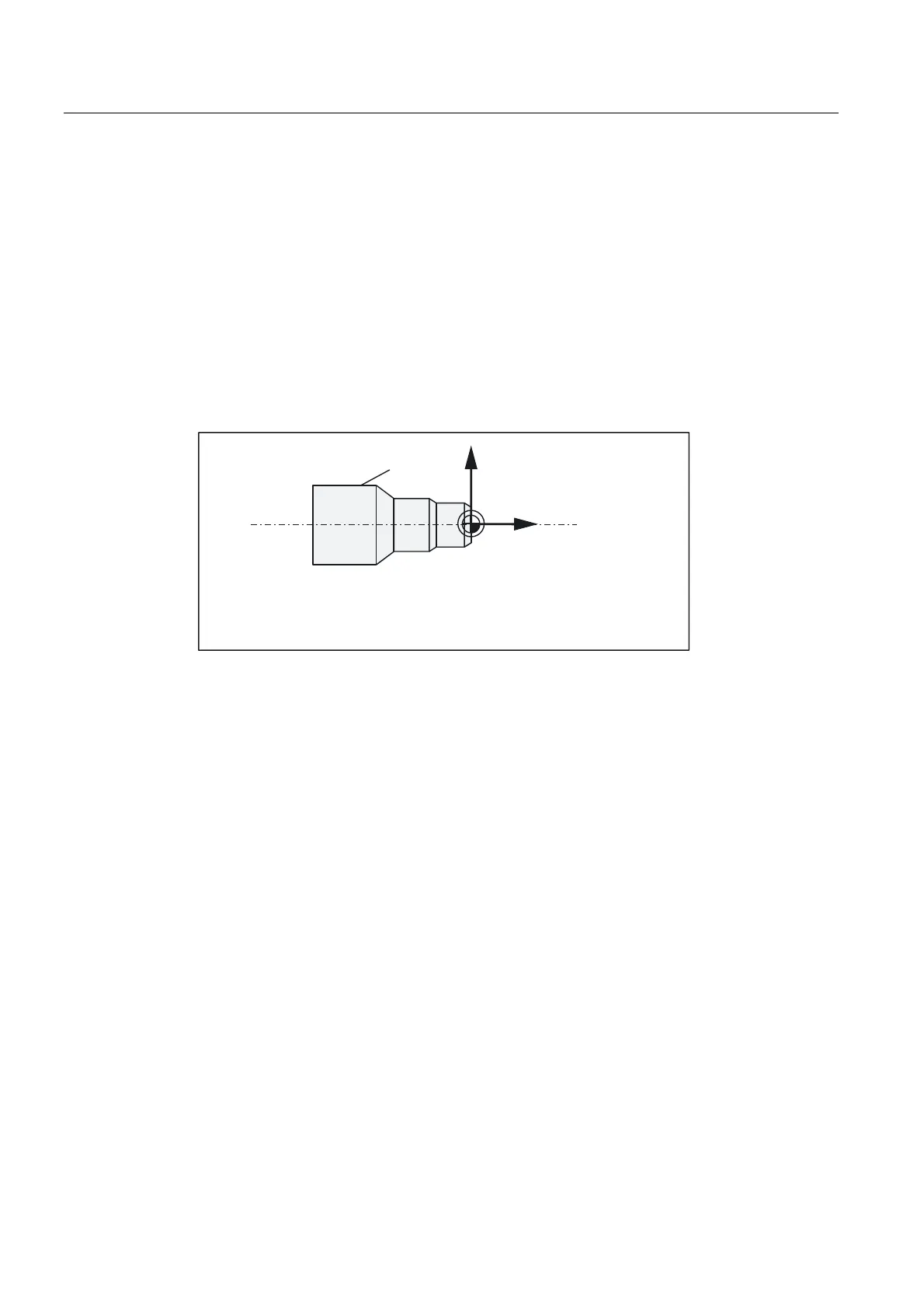
Workpiece coordinate system (WCS)
To describe the geometry of a workpiece in the workpiece program, a right-handed, right-
angled coordinate system is also used.
The workpiece zero can be freely selected by the programmer in the Z axis. In the X axis, it
lies in the turning center.
: ZRUNSLHFH]HUR
:RUNSLHFH
=
:
:RUNSLHFH
;
:RUNSLHFH
Figure 1-4 Workpiece coordinate system
Relative coordinate system
In addition to the machine and workpiece coordinate systems, the control system provides a
relative coordinate system. This coordinate system is used for setting reference points that
can be freely selected and have no influence on the active workpiece coordinate system. All
axis movements are displayed relative to these reference points.