Removing
;
;
;
;
6
3RUW
3RUW
++
;
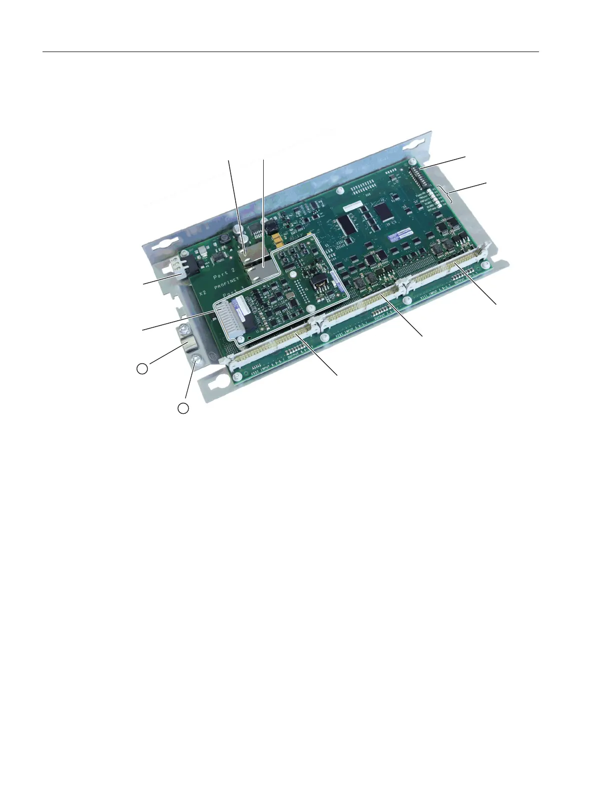
352),1(7;
① Protective conductor connection
② Shield support
Figure 4-23 PP 72/48D 2/2A PN interfaces
Procedure:
1. Switch-off the control: Completely switch off the system. Check that the system is in a no-
voltage condition and is locked-out so that it cannot be switched on again without the
appropriate authorization.
2. Access the control cabinet where the module is located.
3. Using a multimeter, check the X1 power supply to ensure that the system really is in a no-
voltage condition.
4. If it has not already been done, label all connectors that lead to the module now. Only then,
can it be ensured that the cables are not interchanged.
5. Withdraw the power supply X1.
6. Insert connector X3 for the analog inputs/outputs.
7. Release the connectors of the ribbon cables (X111, X222, X333) on the module that are
used to connect the digital inputs and outputs.
8. Remove the strain relief of the PROFINET cables of interfaces X2.
9. Remove the PROFINET cables from interface X2 (port 1 and port 2).
10.Remove the shield support ②, if available.
Service cases - hardware
4.6 I/O modules
Software and hardware
116 Service Manual, 08/2018, 6FC5397-5DP40-6BA1

 Loading...


