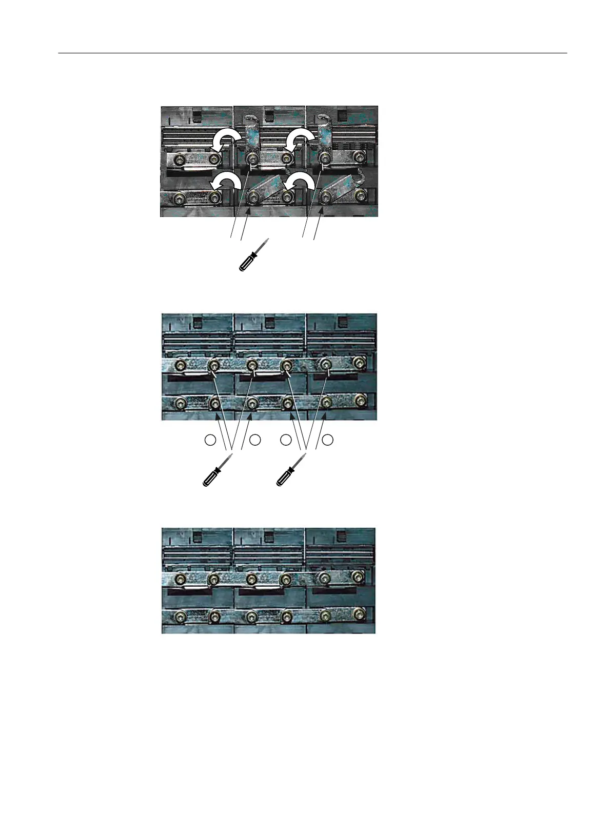
4. Release the Torx screws and connect the DC link busbar.
5. Tighten the Torx screws of the DC link busbars, observe the correct sequence.
6. Place the red jumper plug on the electronics busbar until it clicks into place.
7. Place the 24 V terminal adapter on the electronics power supply busbar until it clicks into
place.
8. Close the protective cover of the DC link voltage.
9. Reconnect motor connections X1 and X2 - if available - to the module.
10.Insert the DRIVE-CLiQ cables that were previously withdrawn into sockets X200 - X202.
Service cases - hardware
4.12 Single Motor Modules
Software and hardware
Service Manual, 08/2018, 6FC5397-5DP40-6BA1 179

 Loading...


