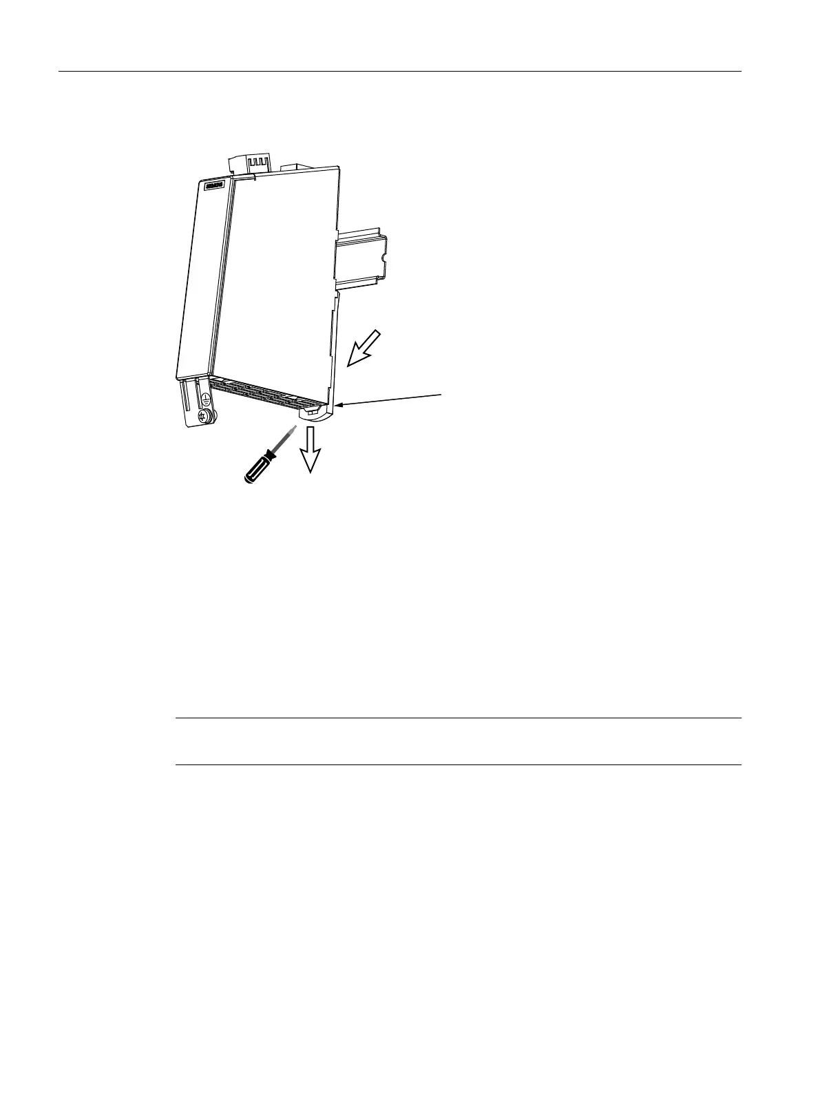
Removing
3XVKWKHOXJGRZQZDUGV
6ZLYHOWKHPRGXOHWRWKHIURQW
0RXQWLQJVOLGH
Figure 4-51 Removing the SMC10/SMC20
Procedure:
1. Withdraw the electronics power supply connector X524 and label.
2. Unscrew the encoder connecting cable at X520 or X521 / X531, if required, also the shield
connection.
3. Withdraw the DRIVE-CLiQ cable X500 and write the slot designation on the cable.
4. Release the protective conductor connection and write the position designation on the cable.
5. Push the lug downwards.
6. Swivel the module to the front.
Note
The 50 mm ventilation clearances above and below the components must be observed.
Service cases - hardware
4.16 Sensor Modules Cabinet
Software and hardware
204 Service Manual, 08/2018, 6FC5397-5DP40-6BA1

 Loading...


