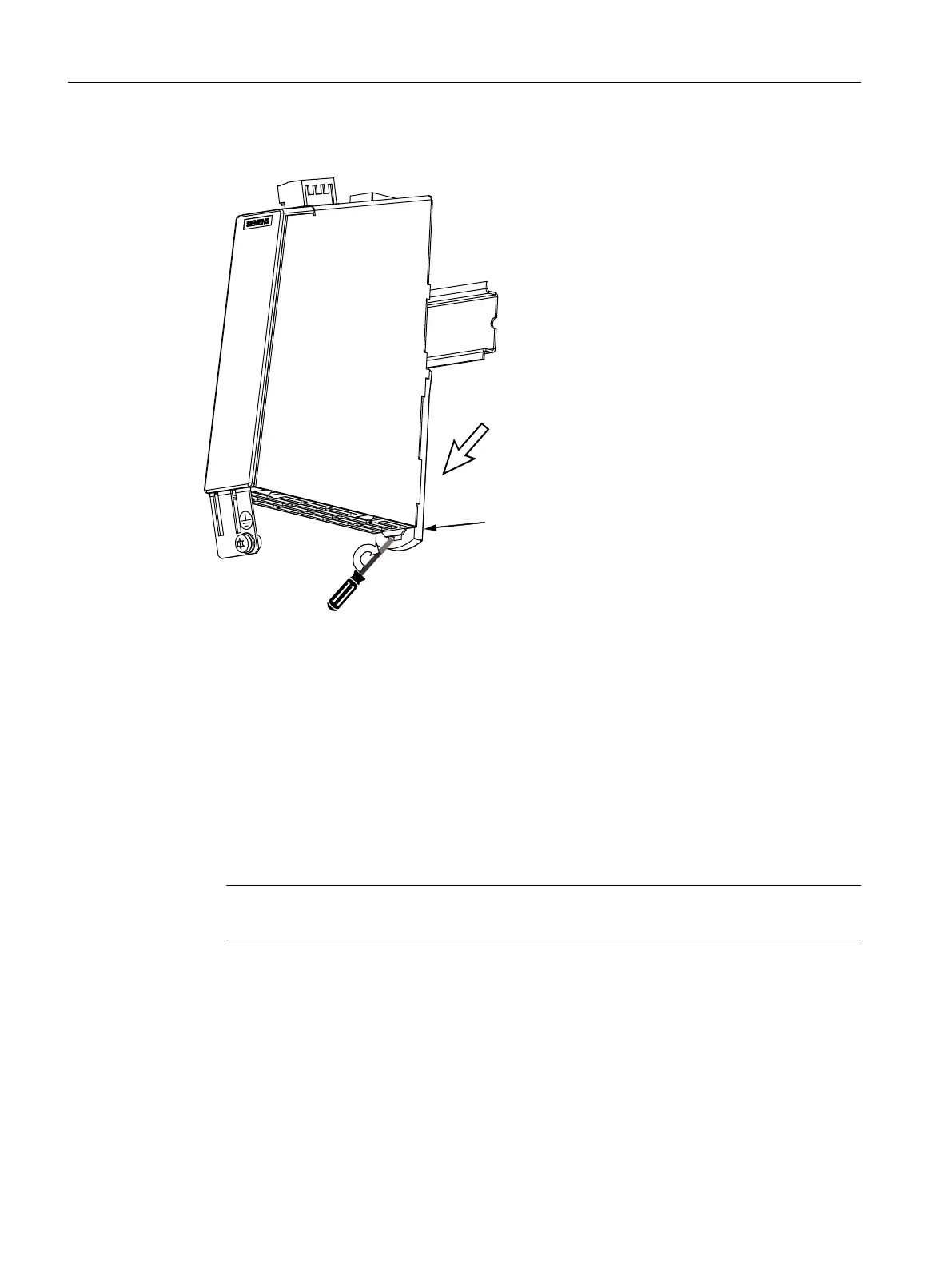
Removing
6ZLYHOWKHPRGXOHWRWKHIURQW
0RXQWLQJVOLGH
5RWDWHDVFUHZGULYHUZLWKDZLGHEODGHWRPP
LQWKHVORWRIWKHPRXQWLQJVOLGHWKURXJKrRU
DOWHUQDWLYHO\SUHVVWKHOXJGRZQZDUGV
Figure 4-53 SMC30 removal
Procedure:
1. Before withdrawing it, label the connector X524 for the electronics power supply.
2. Screw on the encoder connecting cable to X520 or X521 / X531, if required, also the shield
connection.
3. Release the protective conductor connection and write the position designation on the cable.
4. Slide the lug downwards.
5. Swivel the module to the front to remove it.
Note
The 50 mm ventilation clearances above and below the components must be observed.
Service cases - hardware
4.16 Sensor Modules Cabinet
Software and hardware
208 Service Manual, 08/2018, 6FC5397-5DP40-6BA1

 Loading...


