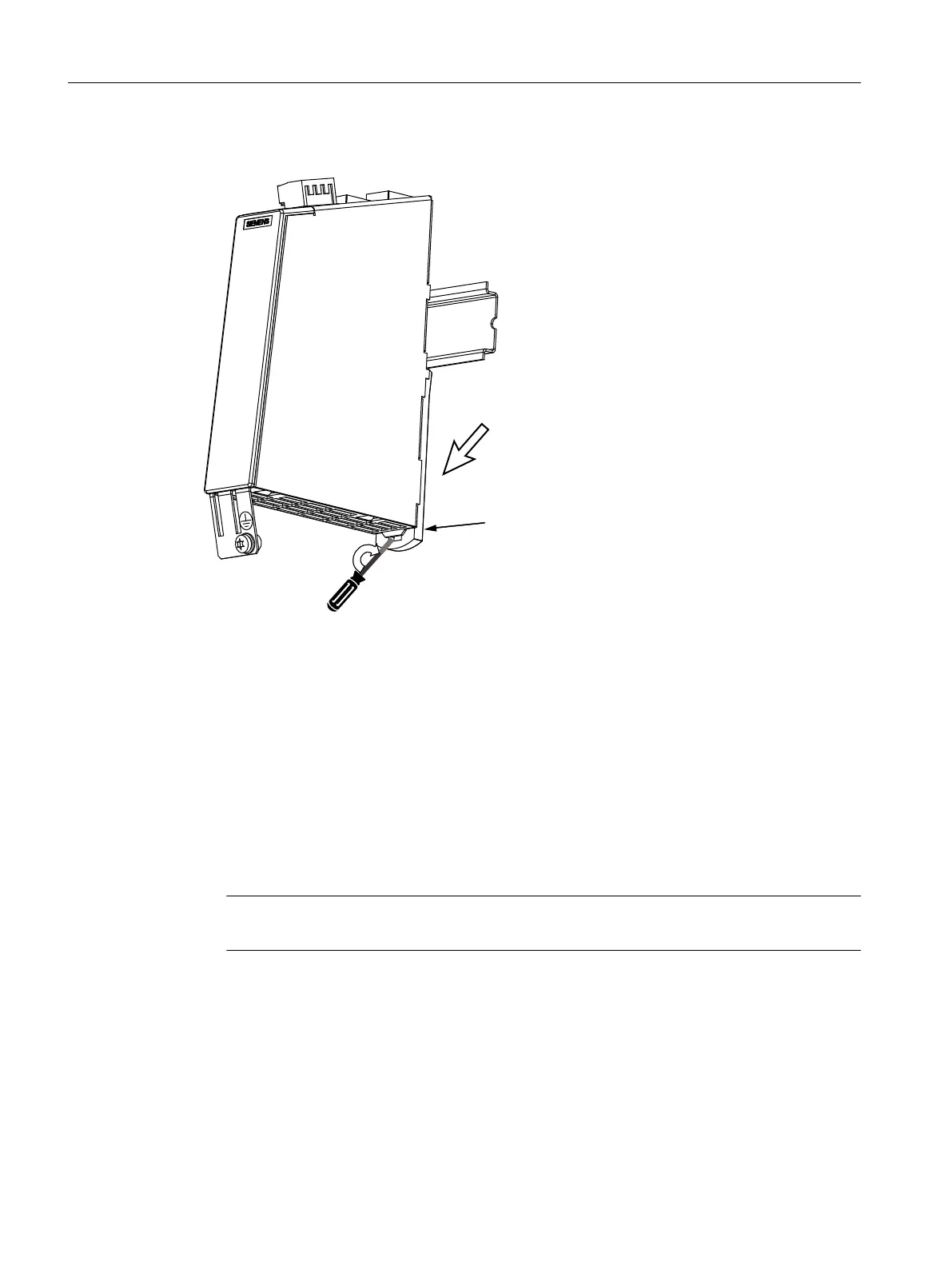
Removing
6ZLYHOWKHPRGXOHWRZDUGWKHIURQW
0RXQWLQJVOLGH
,QVHUWDVFUHZGULYHUZLWKDZLGHEODGHWRPP
LQWKHVORWRIWKHPRXQWLQJVOLGHUURWDWHWKURXJK
rದDOWHUQDWLYHO\SXVKWKHOHDGGRZQZDUG
Figure 4-56 SMC40 removal
Procedure:
1. Before withdrawing it, label the connector X524 for the electronics power supply.
2. Unscrew the encoder connecting cables X520/x.
3. Label the DRIVE-CLiQ cables X500/x and withdraw them.
4. Release the protective conductor connection and write the position designation on the cable.
5. Slide the lug downwards.
6. Swivel the module to the front to remove it.
Note
The 50 mm ventilation clearances above and below the components must be observed.
Service cases - hardware
4.16 Sensor Modules Cabinet
Software and hardware
212 Service Manual, 08/2018, 6FC5397-5DP40-6BA1

 Loading...


