3URWHFWLYHFRQGXFWRU
FRQQHFWLRQ01P
6WUDLQUHOLHI;DQG
;
;
;;6
;
;;
6
;;;;
++
++
;
;;
;;;;;
;;;
;
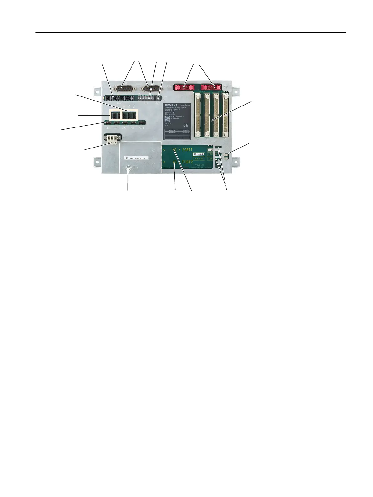
X1 24 VDC power supply
X2 / X3 PROFINET interfaces
X30 Interface for rotary switch feed override
X31 Interface for rotary switch spindle override
X40/X41 Digital inputs (24 V)
X51 / X52 / X55 Digital inputs (TTL)
X58 / X57 / X56 / X53 /
X54
Digital outputs (24 V)
X60 / X62 Handwheel
X61 Reserved
X111 / X112 / X113 /
X114
Key and LED interfaces
H500 / H501 / H502 /
H505
LEDs for status display
S1 DIP switch for the MCP IP address
S2 DIP switch to transfer the handwheel pulse signals
Figure 4-9 MCP Interface PN interfaces
Procedure:
1. Switch-off the control: Completely switch off the system. Check that the system is in a no-
voltage condition and is locked-out so that it cannot be switched on again without the
appropriate authorization.
2. Access the operator panel or control cabinet in which the machine control panel is located.
3. If it has not already been done, label all connectors that are inserted in the module now.
Only then, can it be ensured that the cables are not interchanged.
4. Release the screw connection for power supply X1 and remove this.
Service cases - hardware
4.5 Machine control panels
Software and hardware
Service Manual, 08/2018, 6FC5397-5DP40-6BA1 97

 Loading...


