Service cases - hardware
4.8 SINAMICS S120 Combi
Hardware and Software
124 Service Manual, 03/2011, 6FC5397-5DP40-0BA0
4. Connect the protective conductor.
See also: Protective conductor connection and shield support (Page 116)
5. C
onnect the following connections with the associated screw-type terminals:
X1: Line supply connection
X2 to X4: Motor connection for the S120 Combi with 3 axes
X2 to X5: Motor connection for the S120 Combi with 4 axes
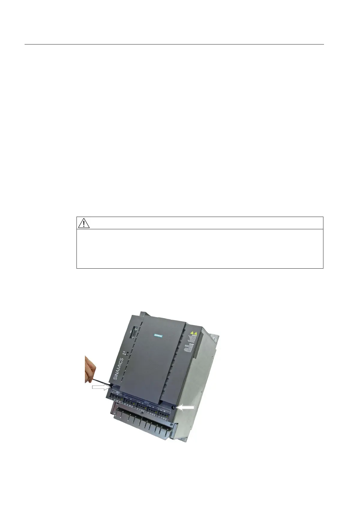
4.8.5 This is how you remove the front panel
Removing the front plate of the S120 Combi
To electrically connect additional components, the front cover of the S120 Combi must be
removed.
DANGER
Risk of electric shock
A hazardous voltage is still present for up to 5 minutes after the power supply has been
switched off.
The front cover must not be opened until this time has elapsed.
Procedure:
1. Use a Torx T20 or slotted 1.2 x 6 screwdriver as tool.
2. Remove the two Torx-slotted screws at the front.

 Loading...


