System description
2.2 System versions horizontal and vertical
Hardware and Software
16 Service Manual, 03/2011, 6FC5397-5DP40-0BA0
⑦ Numerical block
⑧ Menu forward key
⑨ 3/8" threads for additional components
⑩ Protective cover for user interfaces
⑪ X127 Ethernet (service socket)
⑫ Status LED: RDY, NC, CF
⑬ X125 USB interface
⑭ Slot for CompactFlash Card with user data
Figure 2-3 System versions
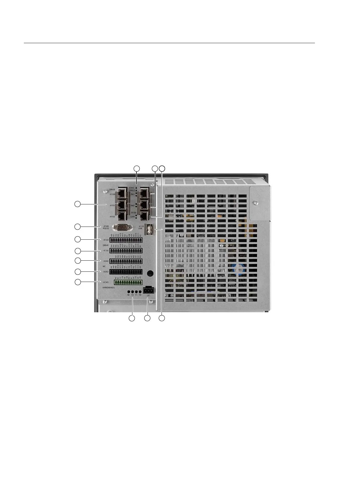
Rear of the PPU 26x.2 and 28x.2
① ② X122, X132 Digital inputs/outputs, drive
③ ④ X242, X252 Digital inputs/outputs, NC
⑤ X143 Handwheels
⑥ M, T2, T1, T0 Measuring sockets
⑦ X1 Power supply
⑧ X135 USB interface: For service purposes only
⑨ X130 Ethernet LAN
⑩ PN 1, PN 2 PLC I/O Interface
⑪ SYNC, FAULT Status LEDs
⑫ X100, X101, X102 DRIVE-CLIQ interfaces
⑬ X140 Serial interface RS232
Figure 2-4 Interfaces on the rear side of the PPU

 Loading...


