Service cases - hardware
4.16 Terminal Modules
Hardware and Software
Service Manual, 03/2011, 6FC5397-5DP40-0BA0
197
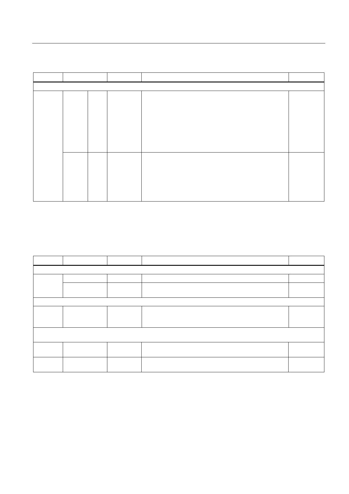
LED Color State Description, cause Remedy
Fail-safe inputs / double inputs
LED
x
–
–
–
–
LED
x+1
Red
–
Red
–
Continuous
light
–
Continuous
light
–
NC contact / NC contact
1)
: (z = 0..9, x = 0, 2, ..18)
Different signal states at input x and x+1
No signal at input x and no signal at input x+1
NC contact / NO contact
1)
: (z = 0..9, x = 0, 2, ..18)
Same signal states at input x and x+1
No signal at input x and a signal at input x+1
–
F_DI z
(input x,
(x+1)+,
(x+1)-)
LED
x
Green
Green
LED
x+1
Green
Green
Continuous
light
Continuous
light
NC contact / NC contact
1)
: (z = 0..9, x = 0, 2, ..18)
A signal at input x and a signal at input x+1
NC contact / NO contact
1)
: (z = 0..9, x = 0, 2, ..18)
A signal at input x and no signal at input x+1
–
1)
Inputs x+1 (DI 1+, 3+, .. 19+) can be set individually via parameter p10040 (TM54F).
p10040 (TM54F) = 0: Input x+1 is an NC contact.
p10040 (TM54F) = 1: Input x+1 is an NO contact.
Factory setting: p10040 (TM54F) = 0 for all inputs x+1.
LED Color State Description, cause Remedy
Single digital inputs, not fail-safe
– Off No signal at digital input x (x = 20..23) – DI x
Green Continuous
light
Signal at digital input x –
Fail-safe digital outputs with associated readback channel
F_DO y
(0+..3+,
0-..3-)
Green Continuous
light
Output y (y=0 .. 3) has a signal –
Readback input DI 2y for output F_DO y (y = 0..3) for test stop.
The status of the LEDs also depends on the type of external circuit.
DI 2y – Off One of the two output lines y+ or y- or both lines of output y
have a signal
–
Green Continuous
light
Both output lines y+ and y- have no signal –

 Loading...


