EasyManuals Logo

Siemens SINUMERIK 840D sl Operation/Programming

Siemens SINUMERIK 840D sl
443 pages
To Next Page IconTo Next Page
To Previous Page IconTo Previous Page
Page #19 background imageLoading...
Page #19 background image
1
08/2005 Introduction
1.2 Workstation
1
Siemens AG, 2005. All rights reserved
SINUMERIK 840D sl Operation/Programming ShopTurn (BAT) – 08/2005 Edition 1-19
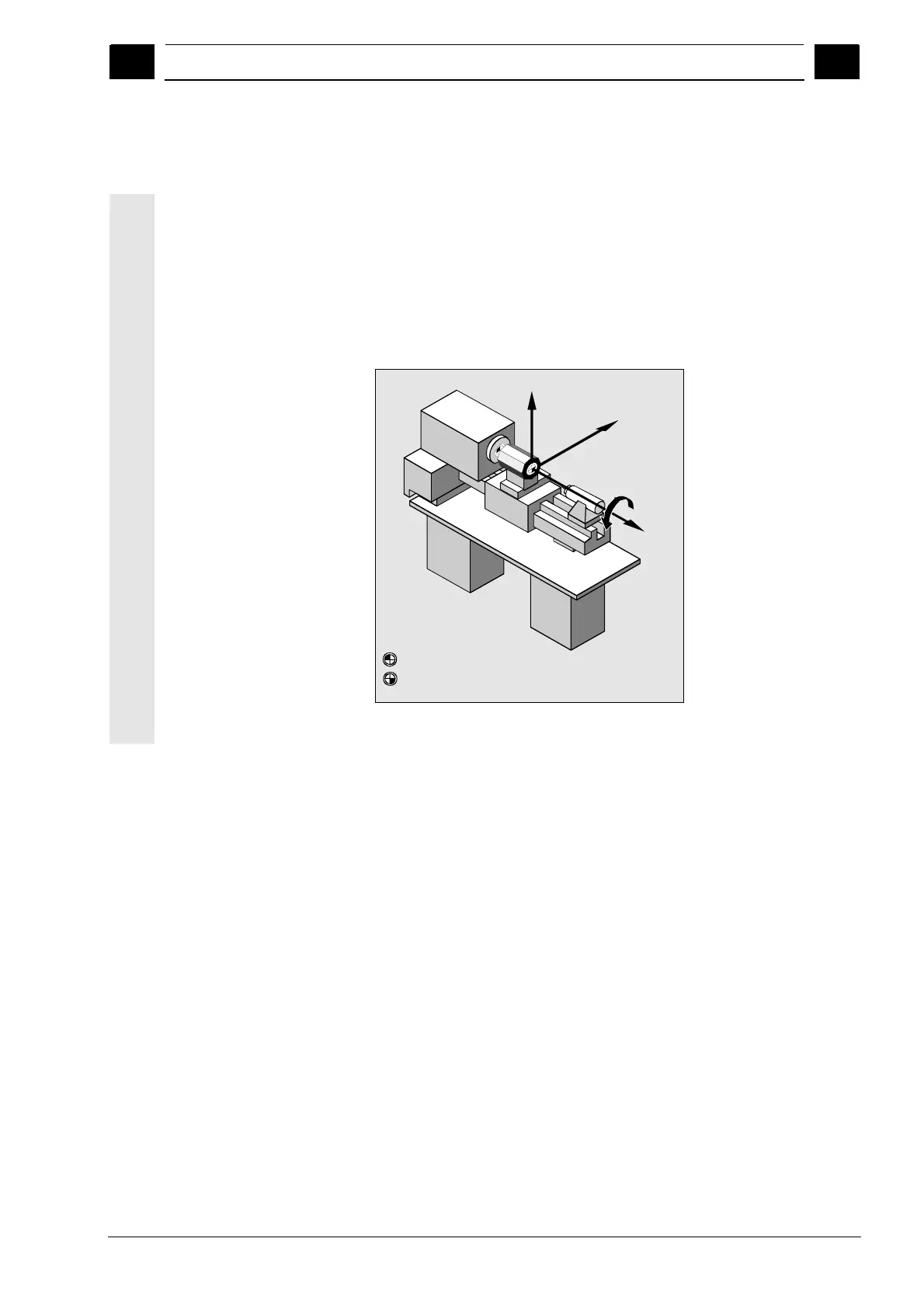
1.2.1 Coordinate system
When machining a workpiece on a lathe, one basically uses a right-
angled coordinate system. This consists of the three coordinate axes
X, Y, and Z which are parallel to the machine axes. The coordinate
axis Y does not have to be set up. Spindle axis Z is an independently
rotating axis and is designated with the letter C.
The positions of the coordinate system and the machine zero depend
on the type of machine used.
W
M
X+
Z+
Y+
W = Workpiece zero
C
M = Machine zero
Position of the coordinate system, machine zero
and workpiece zero (example)

Table of Contents

Other manuals for Siemens SINUMERIK 840D sl

Questions and Answers:

Question and Answer IconNeed help?

Do you have a question about the Siemens SINUMERIK 840D sl and is the answer not in the manual?

Siemens SINUMERIK 840D sl Specifications

General IconGeneral
Control TypeCNC
Number of AxesUp to 31
Max Number of Channels10
InterfacesEthernet, PROFIBUS, PROFINET, USB
Interpolation5-axis interpolation
Operating Temperature0°C to 45°C
Relative HumidityUp to 95% (non-condensing)
DisplayTFT color display, various sizes
Programming LanguagesDIN/ISO
Safety FeaturesSafety Integrated
PLCIntegrated PLC S7-300
Drive InterfaceSINAMICS S120
Data StorageCF card, USB
Operating SystemWindows-based

Related product manuals