EasyManuals Logo

Siemens SINUMERIK 840D sl Operation/Programming

Siemens SINUMERIK 840D sl
443 pages
To Next Page IconTo Next Page
To Previous Page IconTo Previous Page
Page #271 background imageLoading...
Page #271 background image
5
08/2005 ShopTurn Functions
5.6 Contour millin
g
5
Siemens AG, 2005. All rights reserved
SINUMERIK 840D sl Operation/Programming ShopTurn (BAT) – 08/2005 Edition 5-271
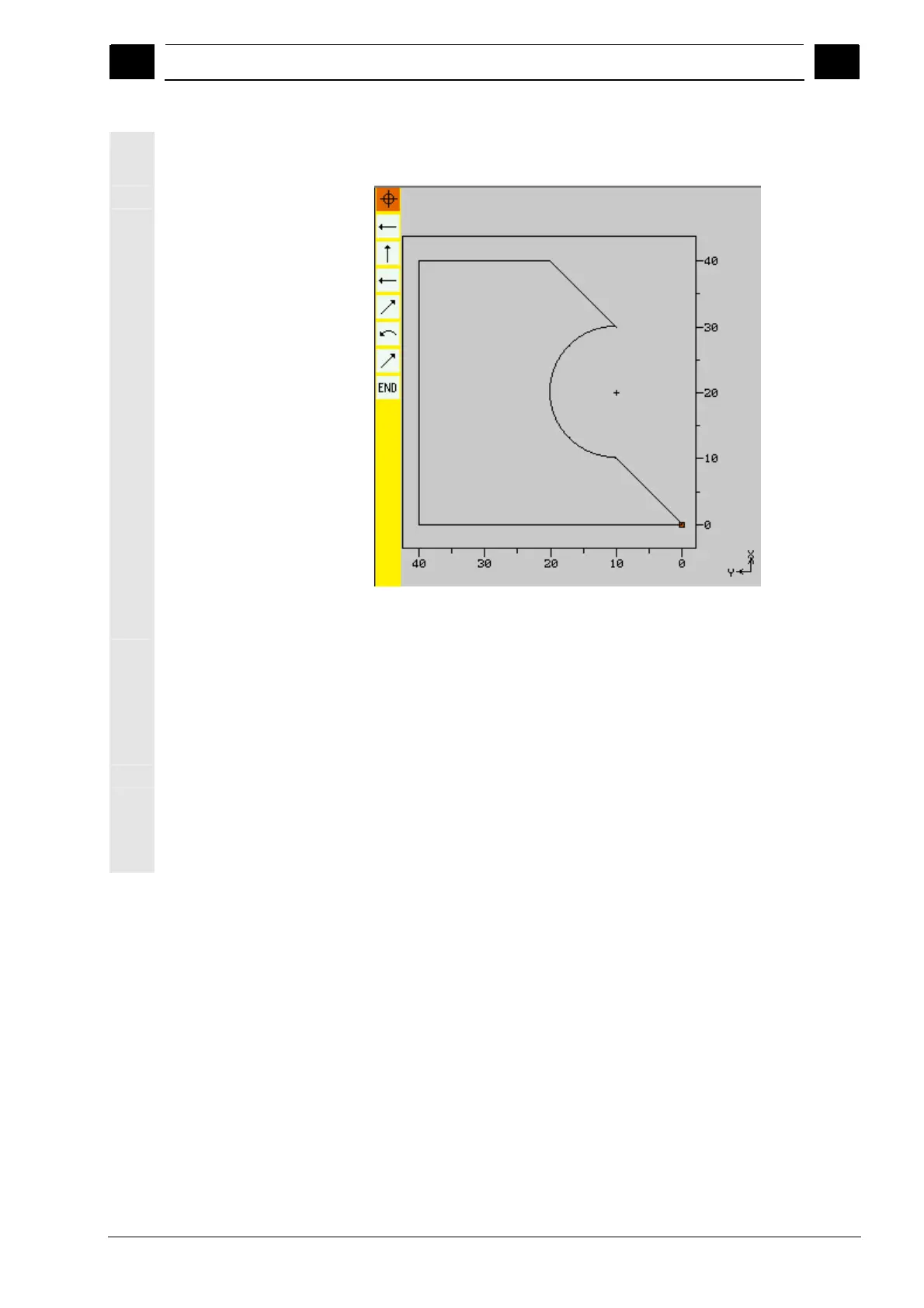
Graphic representation
The progress of contour programming is shown in broken-line
graphics while the contour elements are being entered.
Graphical presentation of the contour during contour milling
When the contour element has been created, it can be displayed in
different line styles and colors:
Black: Programmed contour
Orange: Current contour element
Green dashed: Alternative element
Blue dotted: Partially defined element
The scaling of the coordinate system is adjusted automatically to
match the complete contour.
The position of the coordinate system is displayed in the graphics
window.

Table of Contents

Other manuals for Siemens SINUMERIK 840D sl

Questions and Answers:

Question and Answer IconNeed help?

Do you have a question about the Siemens SINUMERIK 840D sl and is the answer not in the manual?

Siemens SINUMERIK 840D sl Specifications

General IconGeneral
Control TypeCNC
Number of AxesUp to 31
Max Number of Channels10
InterfacesEthernet, PROFIBUS, PROFINET, USB
Interpolation5-axis interpolation
Operating Temperature0°C to 45°C
Relative HumidityUp to 95% (non-condensing)
DisplayTFT color display, various sizes
Programming LanguagesDIN/ISO
Safety FeaturesSafety Integrated
PLCIntegrated PLC S7-300
Drive InterfaceSINAMICS S120
Data StorageCF card, USB
Operating SystemWindows-based

Related product manuals