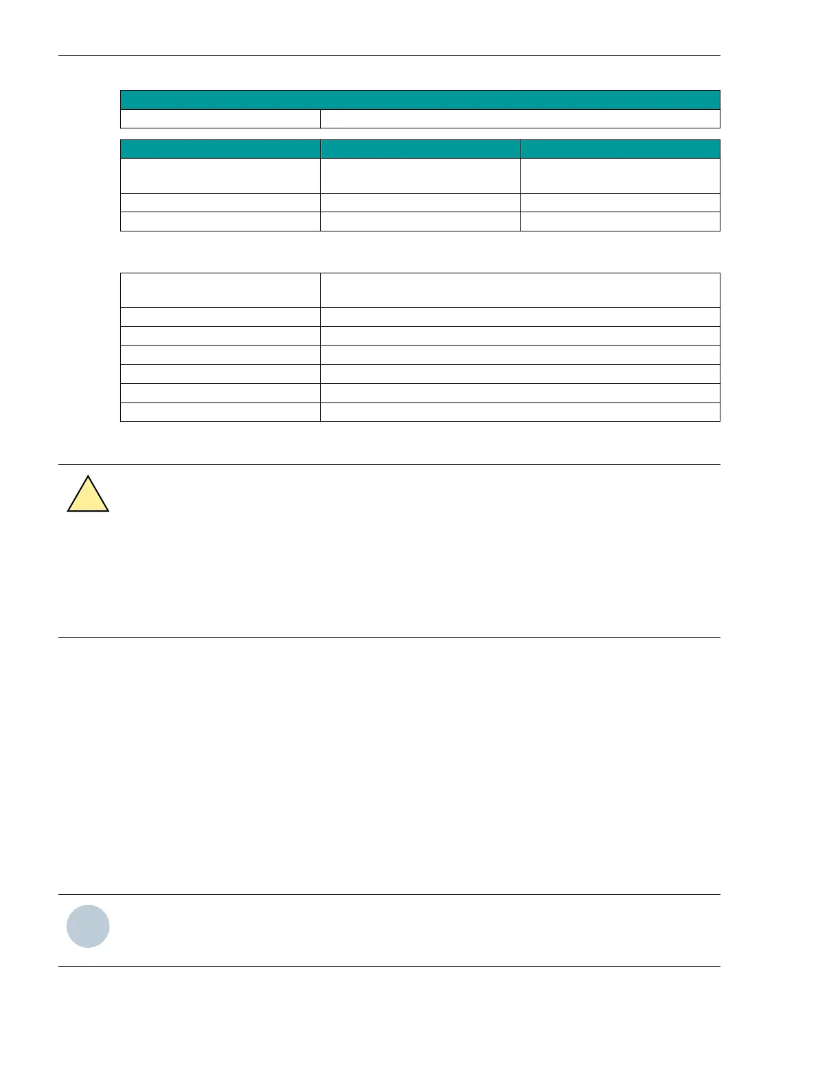
Distance 24 km
Laser class 1 as per EN 60825-1/-2 With the use of 9 µm/125 µm optical fibers
Transmitter Power Minimum Maximum
Transmitter power coupled in
singlemode optical fibers
-15 dBm -8 dBm
Receiver sensitivity -8 dBm -31dBm
Optical budget 16 dB –
SFP with Electrical Interface
Description SFP with RJ45 connector, for Ethernet protocols via an electrical inter-
face
Product code P1Z3201
Connector type RJ45
Baud rate 100 Mbit/s
Protocol See information for the module ETH-BD-2FO
Max. line length 20 m with Ethernet patch cable CAT 6 S/FTP, F/FTP, or SF/FTP
Interface design Corresponds to IEEE 802.3, 100Base-TX
Removing SFP Pluggable Transceivers
CAUTION
Risk of burns due to high temperatures of the SFP pluggable transceivers
Noncompliance with the safety notes may result in medium or light injuries.
²
The SFP pluggable transceivers can be disconnected and plugged in while in operation. Siemens
recommends switching off the device.
²
Allow the SFP pluggable transceiver to cool as much as possible.
✧ Remove the connecting cables or the dust protection cap that was plugged on in the delivery state from
the SFP pluggable transceiver.
✧ In order to release the interlocking, open the bracket on the SFP pluggable transceiver.
✧ Pull on the bracket in order to pull the SFP pluggable transceiver out of the slot. The removal must be
possible with free movement and without great exertion of force.
✧ Provide the SFP pluggable transceiver with the dust protection cap so that the optics are protected from
contamination.
Mounting SFP Pluggable Transceivers
✧
Check whether the bracket on the SFP pluggable transceiver is closed.
The bracket must be closed.
✧ Insert the pluggable transceiver into the slot until it audibly locks in place.
The SFP is securely fixed in the slot.
NOTE
Check for secure positioning of the transceiver in the slot and whether it is locked in place in order to avoid
unintentional removal by pulling on the connection line.
Plug-In Modules
4.2 Communication Modules
178 SIPROTEC 5, Hardware Description, Manual
C53000-G5040-C002-M, Edition 12.2021

 Loading...


