The following cable cross-sections can be used for the connection of single cables:
Cable cross-section
AWG (American Wire Gauge) 20-14 (0.5 mm
2
to
2.5 mm
2
(0.0008 in
2
to 0.0039 in
2
)) solid
or bare stranded wire with or without UL listed boot-
lace ferrule
Use AWG 14 (2,5 mm
2
(0.0039 in
2
)) for currents from
5 A to 10 A.
Use copper conductors only, at least certified for a
temperature of +105 °C (221 °F).
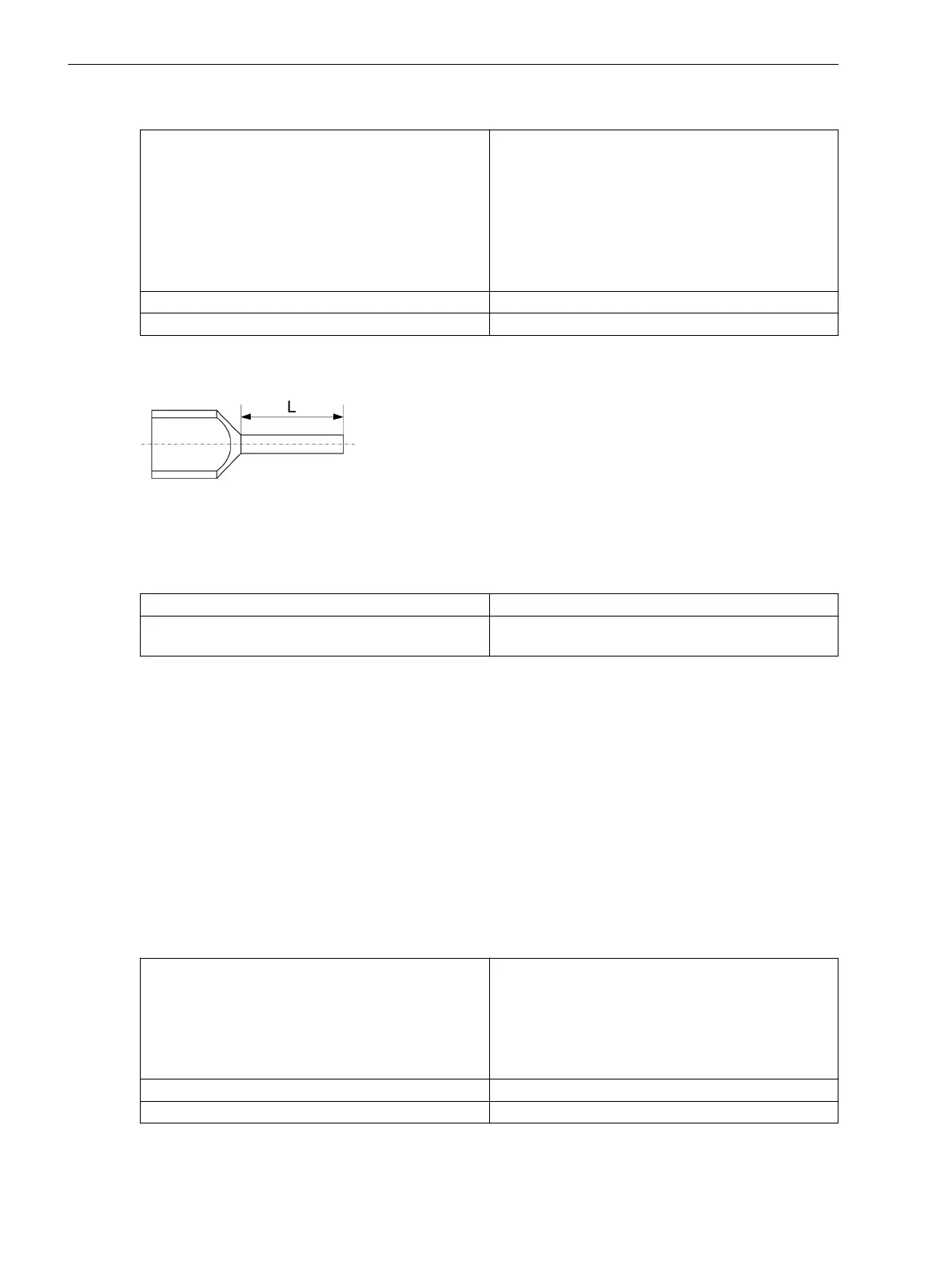
Bootlace ferrule with plastic shroud L = 12 mm (0.47 in)
Stripped length (for use without bootlace ferrule) 12 mm (0.47 in), only copper lines may be used.
Single cables and bridges can be connected together for horizontally arranged clamping points. Note that
adjacent bridges are installed reciprocally.
[dw_bootlace_ferrule, 1, en_US]
Figure 5-31 Twin Bootlace Ferrules
Mechanical Requirements
The fasteners and their associated components are designed for the following mechanical requirements:
Permissible tightening torque at clamping screw
1.0 Nm
Permissible tensile force for each connected
conductor
50 N following IEC 60947-1 (VDE 660, part 100)
Connections of Voltage Terminals with Screw Connection
For connection of the following modules, Phoenix terminals are used (see Figure 5-24):
•
Power-supply module PS203
•
Plug-in module assembly with integrated power supply CB202
•
Input module IO230, IO231, IO233
•
Input and output module IO110, IO112, and IO113
•
Measuring-transducer modules ANAI
•
Temperature measurement module IO111
Connection Elements and Conductor Cross-Sections
The following cross-sections can be used for the connection of single cables:
Cable cross-section
AWG (American Wire Gauge) 22-12 (0.5 mm
2
to
2.5 mm
2
solid (0.0008 in
2
to 0.0039 in
2
))
or bare stranded wire or with UL listed bootlace
ferrules
Approved for at least a temperature of +105 °C (221
°F)
Bootlace ferrule with plastic shroud L = 8 mm to 10 mm
Stripped length (for use without bootlace ferrule) 10 mm (0.39 in), only copper lines may be used.
5.7.3.2
Working on the Device
5.7 Installing Current and Voltage Terminals
218 SIPROTEC 5, Hardware Description, Manual
C53000-G5040-C002-M, Edition 12.2021

 Loading...


