[dw_winkel-020414-01, 1, --_--]
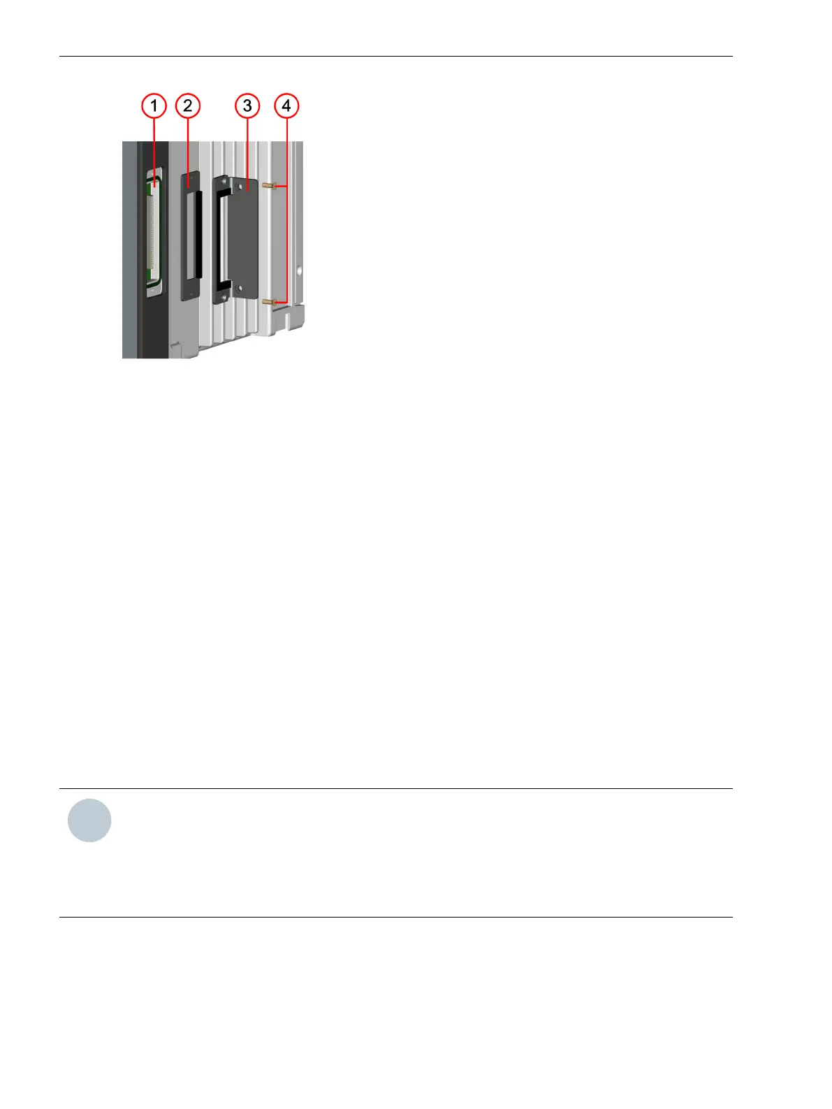
Figure 5-4 Sealing Plate and Adaptor Bracket for the Expansion Module of the 1st Device Row
(1) Device bus of the outermost right expansion module of the 1st device row
(2) Sealing plate
(3) Adaptor angle
(4) 2 mounting screws
Installation and Commissioning
²
Reinstall the plastic screw covers.
²
Refasten the terminal blocks and the necessary communication lines.
²
Connect the current and voltage blocks of the expansion module.
²
Connect any available plug-in modules.
²
Use the supplied grounding cable to connect the expansion module with the device and reconnect the
device to service ground.
²
Extend the device configuration in DIGSI and load this configuration to the device.
²
Resume operation of the device.
Surface-Mounted Devices with Integrated On-Site Operation Panel
Basic Rules for Expanding
NOTE
Prepare the following tools for the device expansion:
•
Phillips screwdriver size PZ1 and PZ2
•
Screwdriver DIN 4 x 0.8
•
During assembly, use the prescribed torques (see chapter 6.13 Design Data).
Comply with the following basic rules when extending devices:
•
Always fit the base module on the right in the 1st device row.
•
Always fit the expansion modules from right to left.
•
Always fit the on-site operation panel of the base module on the left.
5.2.2
5.2.2.1
Working on the Device
5.2 Expanding Modular Devices
188 SIPROTEC 5, Hardware Description, Manual
C53000-G5040-C002-M, Edition 12.2021

 Loading...


