•
Always fit the on-site operation panels of the expansion modules from left to right.
•
Always fit the on-site operation panel of the expansion module with the key switches in the 1st place
next to the on-site operation panel of the base module.
•
Always fit the on-site operation panels without LEDs last.
•
Join the on-site operation panels to one another with 2 mounting brackets.
•
Always install a power-supply module PS203 on the right as the first unit in the 2nd device row.
•
Note that the PS203 must always have the same rated voltage as the base module.
•
Always mount the redundant PS204 power supply module at the position furthest to the right in the
corresponding row when you're looking at it from the front. If a CB202 printed circuit board assembly is
present in the row, the CB202 printed circuit board assembly must always be mounted to the right of the
PS204 printed circuit board assembly (at the outermost position). You will find an example of this in
Chapter 3.1.4.2 Positioning Specifications.
•
Note that the PS204 printed circuit board assembly must always have the same rated voltage as the base
module.
•
In the 2nd device row, you do not need any on-site operation panels, mounting brackets, or distance
frames.
NOTE
When expanding a device in the 1st device row, order 2 mounting brackets that match the width of the
expanded device.
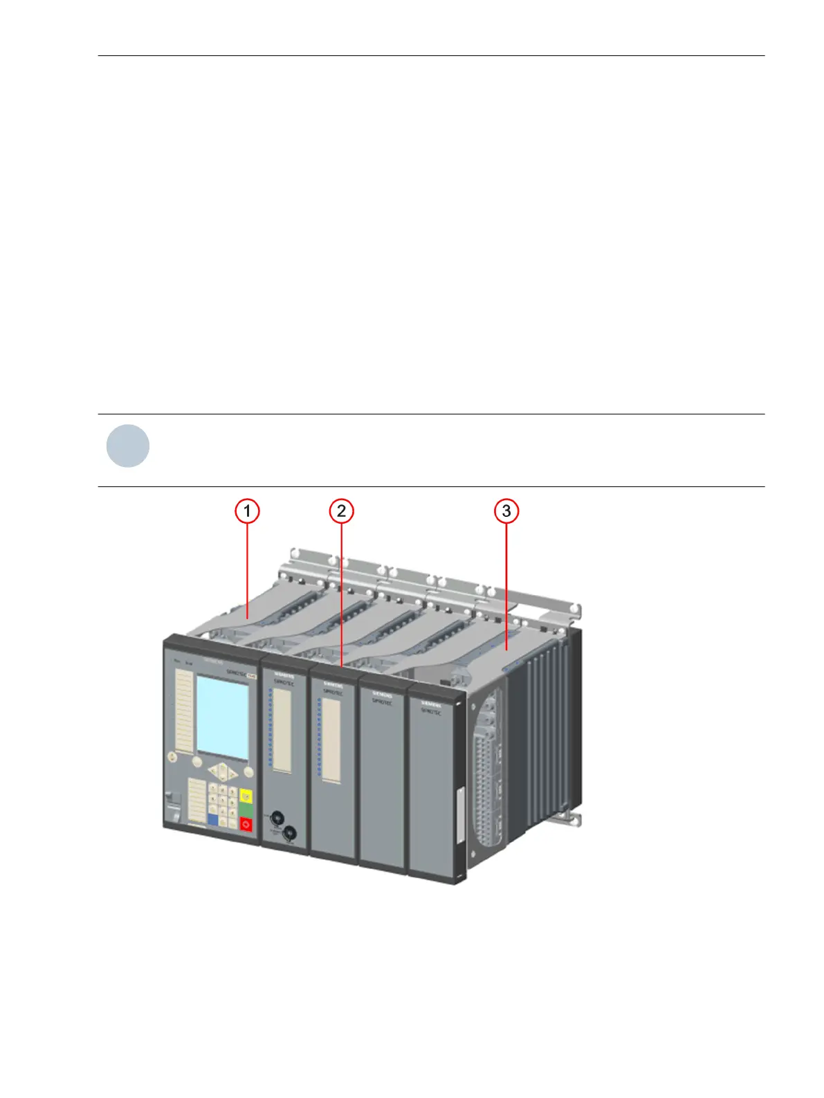
[dwauize1-040211-01.tif, 2, --_--]
Figure 5-5
Device Row
(1) Distance frame
(2) Mounting bracket
(3)
Distance frame on base module rotated by 180
o
Working on the Device
5.2 Expanding Modular Devices
SIPROTEC 5, Hardware Description, Manual 189
C53000-G5040-C002-M, Edition 12.2021

 Loading...


