[dw_2zeauf-020414-01, 1, --_--]
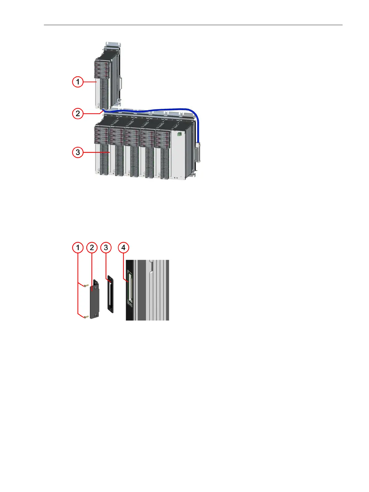
Figure 5-7 Expansion with 2nd Device Row (View of the Installation Level without Showing the On-Site
Operation Panel)
(1) Extreme right expansion module of the 1st device row
(2) Connecting cables
(3) 2nd device row
[dw_winauf-020414-01, 1, --_--]
Figure 5-8 Sealing Plate and Adaptor Bracket for the Expansion Module of the 1st Device Row
(1) 2 fastening screws
(2) Adaptor angle
(3) Sealing plate
(4) Device bus of the outermost left expansion module of the 1st device row
Installation and Commissioning
²
Reinstall the plastic screw covers.
²
Refasten the terminal blocks and the necessary communication lines.
²
Connect the current and voltage blocks of the expansion module.
²
Connect any available plug-in modules.
²
Use the supplied grounding cable to connect the expansion module with the device and reconnect the
device to service ground.
Working on the Device
5.2 Expanding Modular Devices
SIPROTEC 5, Hardware Description, Manual 193
C53000-G5040-C002-M, Edition 12.2021

 Loading...


