Installation and Commissioning
8-197SA522 Manual
C53000-G1176-C119-2
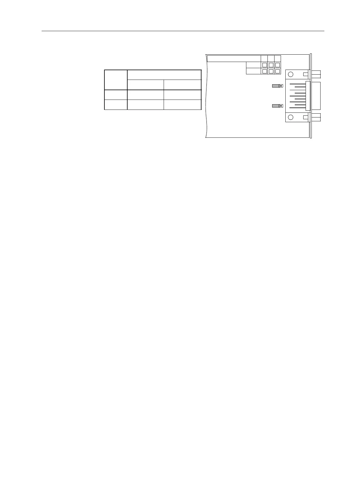
Figure 8-12 Location of the Jumpers for Configuring the Profibus–Interface Terminating
Resistors
To Reassemble
the Device
To reassemble the device, proceed as follows:
o Carefully insert the boards into the case. The installation locations of the boards are
shown in Figure 8-7 and 8-8.
For the model of the device designed for surface mounting, use the metal lever to in-
sert the CPU board. The installation is easier with the lever.
o First insert the plug connectors on the ribbon cable in the input/output modules I/O and
then on the processor module CPU. Be careful not to bend any of the connecting pins!
Do not use force!
o Insert the plug connector of the ribbon cable between the processor module CPU and
the front cover in the socket on the front cover.
o Press the latches of the plug connectors together.
o Replace the front cover and secure to the housing with the screws.
o Replace the covers.
o Re-fasten the interfaces on the rear of the device housing.
This activity is not necessary if the device is for surface mounting.
X3
312
X4
312
Jumper
Terminating resistors
Connected Disconnected
X3 1-2 2-3*
)
X4 1-2 2-3*
)
*
)
Factory Set
C53207-A322-
234
B100
B101

 Loading...


