Installation and Commissioning
8-137SA522 Manual
C53000-G1176-C119-2
o At one end, disconnect the ribbon-cable between the front cover and the CPU board
(å). To disconnect the cable, push up the top latch of the plug connector and push
down the bottom latch of the plug connector. Carefully set aside the front cover.
o Disconnect the ribbon-cables between the CPU board (å) and the I/O boards (ê).
o Remove the boards and set them on the grounded mat to protect them from ESD dam-
age. A greater effort is required to withdraw the CPU board, especially in versions of
the device for surface-mounting, because of the communication connectors.
o Check the jumpers according to Figures 8-9 to 8-12. Change or remove the jumpers
as necessary.
o The order of the boards for housing size
1
/
2
is shown in figure 8-7,
for housing size
1
/
1
refer to figure 8-8.
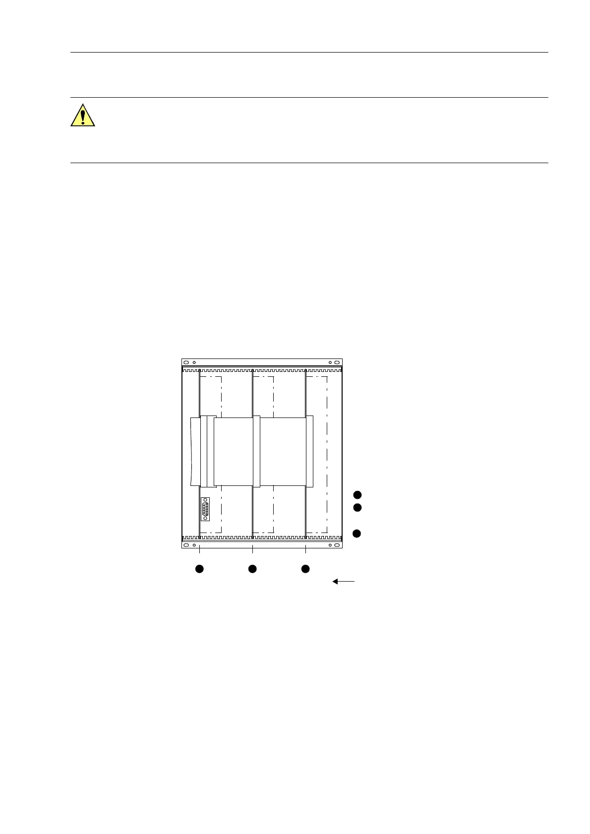
Figure 8-7 Front view of the device with housing size
1
/
2
after removal of the front cover (sim-
plified and scaled down)
Caution!
Electrostatic discharges through the connections of the components, wiring, plugs,
and jumpers must be avoided. Wearing a grounded wrist strap is preferred. Otherwise,
first touch a grounded metal part.
1
2
3
Slot 5 Slot 19 Slot 33
Binary inputs (BI)BI1 to
Input/output printed circuit board I/O-1
Input/output printed circuit board I/O-2
Prozessorbaugruppe
Processor printed circuit board CPU
1 2 3
BI8
(transducers)
with power supply

 Loading...


