2.9.2 Tripping According to French Specification
203
7SA522 Manual
C53000-G1176-C155-3
In address :,QRQGHOD\HG the stage for instantaneous tripping is switched
2)) or 21 continuously.
Trip with Delay The operation of the delayed tripping is determined by three parameters:
•Address SRO7ULS enables a single-pole trip command in case of single-
pole faults if set to 21.
• If set to 21, address SROZLWK, allows a single-pole trip command
only if the threshold ,!7KUHVKROG for the zero current has been surpassed.
Position 2)) allows a single-pole trip command even when ,!7KUHVKROG is
not exceeded. The time delay of “3I0> exceeded” is set at address 7,!
([W.
• If set to 21, address SRO7ULS allows also a three-pole trip command. In
position 2)) the multi-pole pickup is only reported but a three-pole trip command is
not issued (only report). But a single-pole trip command can nevertheless be
issued.
A delayed tripping stage is implemented to allow tripping the dedicated line end in
case the transmission channel is faulted. When undervoltage conditions have been
detected, this stage picks up in one or more phases and after a configured time (ad-
dress 70 and address 77) has elapsed it trips without delay.
The delayed-tripping stage :,GHOD\HG is switched 21 or 2)) - permanently at
address . The setting E\UHFHLYHIDLO only activates this stage if ´!:,UHF
2.µ is not reported as OFF.
To avoid erroneous pickup, phase selection via undervoltage is blocked entirely in the
event of voltage failure (pickup of the fuse failure monitor or of the VT mcb). Moreover
the corresponding phases are equally blocked if another protection function, capable
to detect faults, picks up.
2.9.2.3 Settings
Addresses which have an appended "A" can only be changed with DIGSI, under Ad-
ditional Settings.
The table indicates region-specific presettings. Column C (configuration) indicates the
corresponding secondary nominal current of the current transformer.
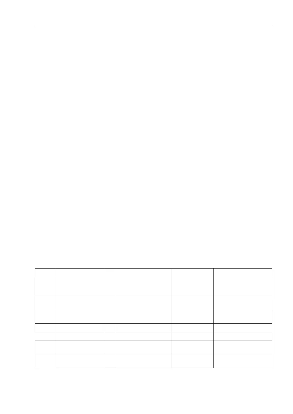
Addr. Parameter C Setting Options Default Setting Comments
2501 FCT Weak Infeed OFF
ECHO only
ECHO and TRIP
ECHO only Weak Infeed function is
2502A Trip/Echo DELAY 0.00 .. 30.00 sec 0.04 sec Trip / Echo Delay after
carrier receipt
2503A Trip EXTENSION 0.00 .. 30.00 sec 0.05 sec Trip Extension / Echo
Impulse time
2504A Echo BLOCK Time 0.00 .. 30.00 sec 0.05 sec Echo Block Time
2505 UNDERVOLTAGE 2 .. 70 V 25 V Undervoltage (ph-e)
2509 Echo:1channel NO
YES
NO Echo logic: Dis and EF on
common channel
2510 Uphe< Factor 0.10 .. 1.00 0.70 Factor for undervoltage
Uphe<

 Loading...


