2 Functions
322
7SA522 Manual
C53000-G1176-C155-3
1)
after three unsuccessful restarts, the device is taken out of service.
2)
DOK = “Device OK” = NC contact of the operational readiness relay = life contact
2.19.1.5 Setting Notes
General The sensitivity of measured value monitor can be modified. Default values are set at
the factory, which are sufficient in most cases. If especially high operating asymmetry
in the currents and/or voltages is to be expected for the application, or if it becomes
apparent during operation that certain monitoring functions activate sporadically, then
the setting should be less sensitive.
The measurement supervision can be switched 21 or 2)) in address
0($685(683(59.
Symmetry
Monitoring
Address %$/$1&(8/,0,7 determines the limit voltage (Phase-to-Phase),
above which the voltage symmetry monitor is effective. Address %$/)$&725
8 is the associated symmetry factor; that is, the slope of the symmetry characteristic
curve. The alarm ´)DLO8EDODQFHµ (FNo. 167) can be delayed at address
7%$/8/,0,7. These settings can only be changed via DIGSI
®
at Additional
Settings.
Address %$/$1&(,/,0,7 determines the limit current, above which the
current symmetry monitor is effective. Address %$/)$&725, is the associ-
ated symmetry factor; that is, the slope of the symmetry characteristic curve. The
alarm ´)DLO,EDODQFHµ (FNo. 163) can be delayed at address 7%$/,
/,0,7. These settings can only be changed via DIGSI
®
at Additional Settings.
Summation
Monitoring
Address Σ,7+5(6+2/' determines the limit current, above which the current
sum monitor is activated (absolute portion, only relative to I
N
). The relative portion (rel-
ative to the maximum conductor current) for activating the current sum monitor is set
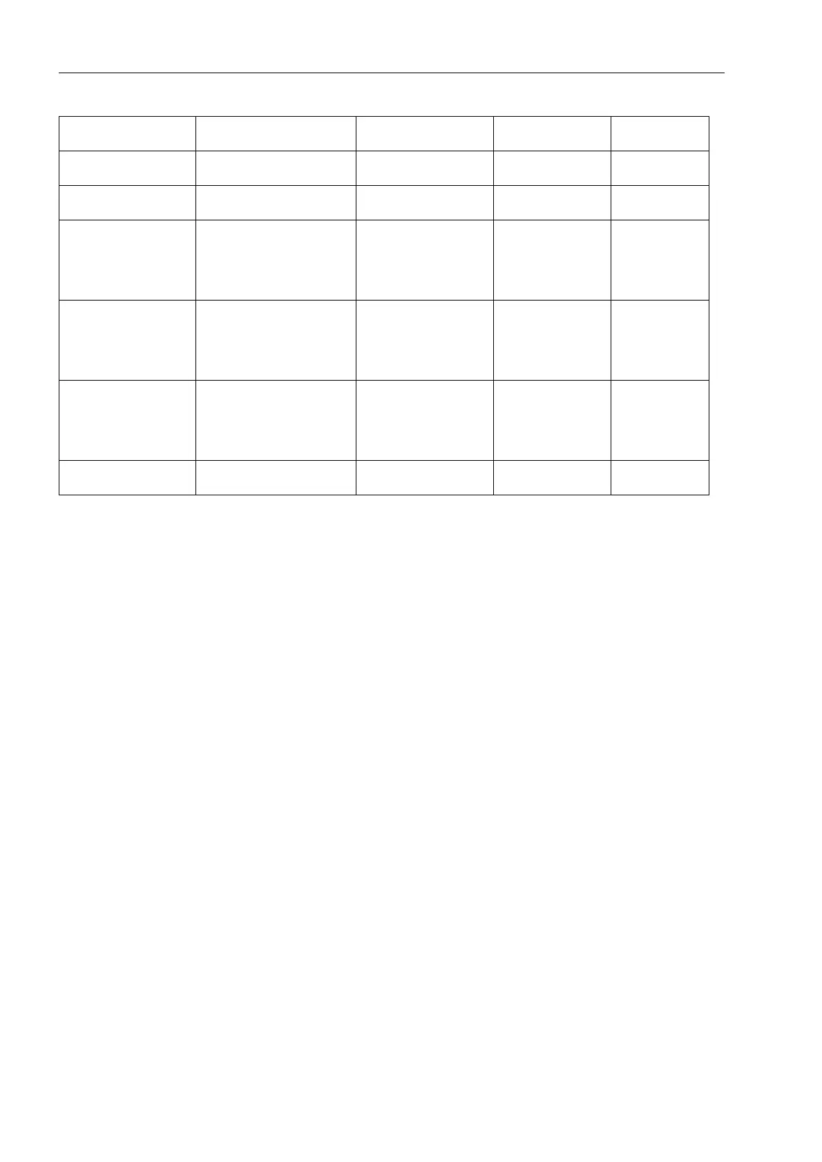
Voltage Symmetry External (power system or
voltage transformer)
Message “Fail U balance”
(167)
As allocated
Voltage phase se-
quence
External (power system or
connection)
Message “Fail Ph. Seq.” (171) as allocated
Measuring voltage fail-
ure, three-phase “Fuse
Failure Monitor”
External (power system or
connection)
Message
Distance protection is
blocked
Undervoltage protection
is blocked
“VT FuseFail>10s”
(169)
as allocated
Voltage failure, one-
/two-phase “Fuse
Failure Monitor”
External (voltage transform-
ers)
Message
Distance protection is
blocked
Undervoltage protection
is blocked
“VT FuseFail>10s”
(169)
As allocated
Voltage failure, three-
phase
external (power system or
connection)
Message
Distance protection is
blocked
Undervoltage protection
is blocked
“Fail U absent” (168) As allocated
Trip Circuit Monitoring External (trip circuit or
control voltage)
Message “FAIL: Trip cir.”
(6865)
as allocated
Monitoring Possible Causes Malfunction Re-
sponse
Alarm (FNo.) Output

 Loading...


