4 Technical Data
462
7SA522 Manual
C53000-G1176-C155-3
4.9 Protection Data Interfaces and Communication Topology (optional)
Protection Data Interfaces
Protection Data Communication
Quantity 1 or 2
- Connection optical fibre Mounting location “D” for one connection or “D” and “E” for two
connections
For flush-mounted case On the rear side
For surface-mounted case At the inclined housing on the case bottom
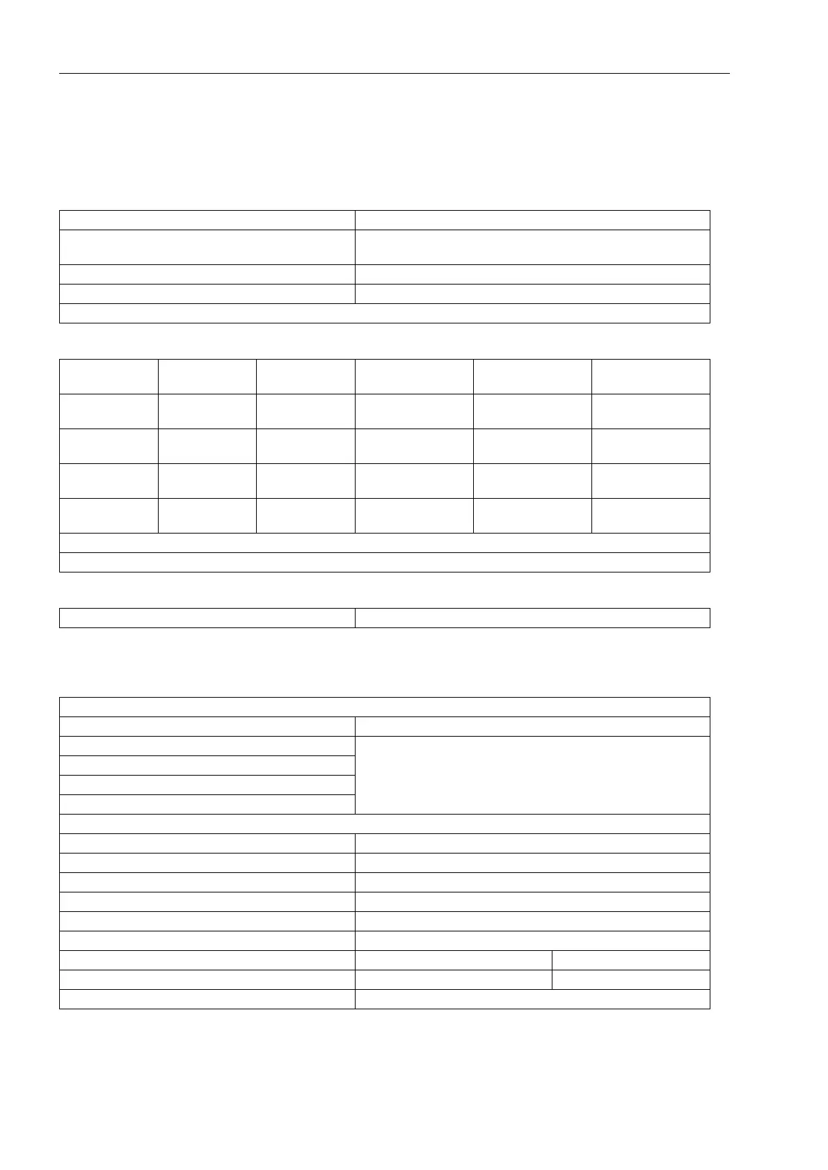
Connection modules for protection data interface, depending on the ordering version:
Module in
Device
Connector Type Fibre Type Optical Wavelength Perm. Path
Attenuation
Distance, Maximum
FO5
1
) ST Multimode
62.5/125µm
820 nm 8 dB 1.5 km 0.95 miles
FO6
2
) ST Multimode
62.5/125µm
820 nm 16 dB 3.5 km 2.2 miles
FO7
2
) ST Monomode
9/125 µm
1300 nm 7 dB 10 km 6.25 miles
FO8
2
) FC Monomode
9/125 µm
1300 nm 18 dB 35 km 22 miles
1
) Laser class I according to EN 60825-1/ -2 using glass fibre 62.5/125 µm
2
) Laser class 3A according to EN 60825-1/ -2
- Character idle state “Light Off”
Direct connection:
Transmission rate 512 kbit/s
Fibre type
Refer to table above
Optical wavelength
Permissible link signal attenuation
Transmission distance
Connection via communication networks:
Communication converter See Appendix A.1, Subsection Accessories
Supported network interfaces G703.1 with 64 kbit/s;
X.21 with 64 or 128 or 512 kbit/s
Connection to communication converter See table above under module FO 5
Transmission rate 64 kbit/s with G703.1
512 kbit/s or 128 kBit/s or 64 kbit/s with X.21
Max. runtime time 0.1 ms to 30 ms Increments 0.1 ms
Max. runtime difference 0.000 ms to 3.000 ms Increments 0.001 ms
Transmission accuracy CRC 32 according to CCITT or ITU

 Loading...


