2 Functions
276
7SA522 Manual
C53000-G1176-C155-3
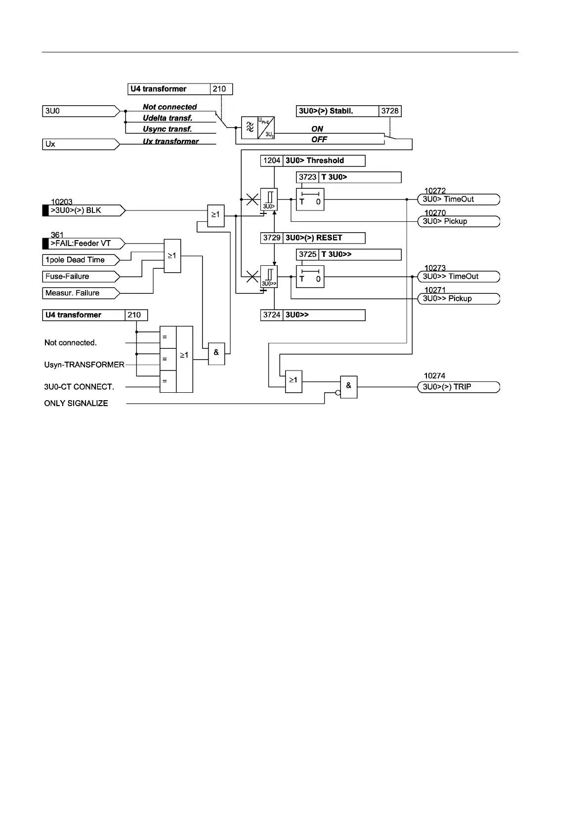
Figure 2-115 Logic diagram of the overvoltage protection for zero sequence voltage
Freely Selectable
Single–phase
Voltage
As the zero sequence voltage stages operate separately and independent from the
other protective overvoltage functions they can be used for any other single–phase
voltage. Therefore the fourth voltage input U
4
of the device must be assigned accord-
ingly (also see Section 2.1.3, “Voltage Transformer Connection”).
The stages can be blocked via a binary input ´!8!!%/.µ. Internal blocking is
not accomplished in this application case.
2.15.2 Undervoltage Protection
Undervoltage
Phase–Earth
Figure 2-116 depicts the logic diagram of the phase voltage stages. The fundamental
frequency is numerically filtered from each of the three measuring voltages so that har-
monics or transient voltage peaks are largely harmless. Two threshold stages 8SK
H and 8SKH are compared with the voltages. If phase voltage falls below a
threshold it is indicated phase-segregated. Furthermore, a general pick-up indication
´8SKH3LFNXSµ ´8SKH3LFNXSµ is given. The drop-out to pick-up ratio is
approx. 1.05.
Every stage starts a time delay which is common to all phases. Expiry of the respective
time delay 78SKH or 78SKH is signalled and results in the trip command
´8SKH75,3µ.
Depending on the configuration of the substations the voltage transformers are
located on the busbar side or on the outgoing feeder side. This results in a different

 Loading...


