4 Technical Data
444
7SA522 Manual
C53000-G1176-C155-3
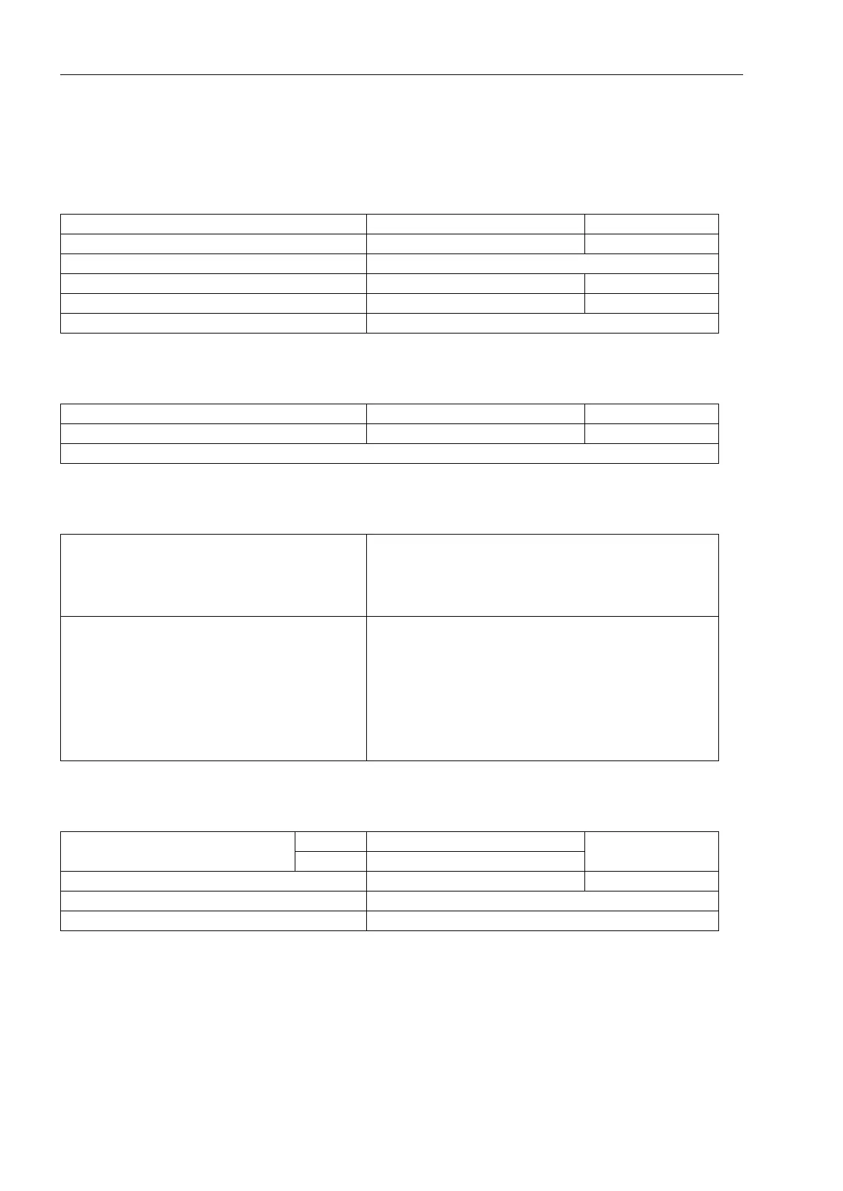
4.2 Distance Protection
Earth Impedance Ratio
Mutual Impedance Ratio
Phase Preferences
Earth Fault Detection
R
E
/R
L
-0.33 to 7.00 Increments 0.01
X
E
/X
L
-0.33 to 7.00 Increments 0.01
Separate for first and higher zones
K
0
0.000 to 4.000 Increments 0.001
PHI (K
0
) -135.00° to +135.00°
Separate for first and higher zones
R
M
/R
L
0.00 to 8.00 Increments 0.01
X
M
/X
L
0.00 to 8.00 Increments 0.01
The matching factors for earth impedance and mutual impedance are valid also for fault location.
For double earth fault in earthed net Block leading phase–earth
Block lagging phase–earth
Release all associated loops
Release only phase-to-earth loops
Release of phase-to-phase loops
For double earth fault in isolated or resonant-earthed
systems
L3(L1) acyclic
L1(L3) acyclic
L2(L1) acyclic
L1(L2) acyclic
L3(L2) acyclic
L2(L3) acyclic
L3(L1) cyclic
L1(L3) cyclic
All associated loops
Earth current 3I
0
>for I
N
= 1 A 0.05 A to 4.00 A Increments 0.01 A
for I
N
= 5 A 0.25 A to 20.00 A
Earth voltage 3U
0
> 1 V to 100 V; ∞ Increments 1 V
Drop-off to pick-up ratio Approx. 0.95
Measuring tolerances for sinusoidal measured values ± 5%

 Loading...


