2 Functions
336
7SA522 Manual
C53000-G1176-C155-3
For this, separate binary inputs are available, which should be treated the same and
configured additionally if necessary. These have a similar significance as the inputs
described above for protection applications and are marked with “CB1 ...” to distin-
guish them, i.e.:
• ´!&%S&ORVHGµ (FNo. 410) for the series connection of the NO auxiliary con-
tacts of the CB,
• ´!&%S2SHQµ (FNo. 411) for the series connection of the NC auxiliary contacts
of the CB,
• ´!&%3ROH/µ (FNo. 366) for the auxiliary contact of pole L1
• ´!&%3ROH/µ (FNo. 367) for the auxiliary contact of pole L2
• ´!&%3ROH/µ (FNo. 368) for the auxiliary contact of pole L3.
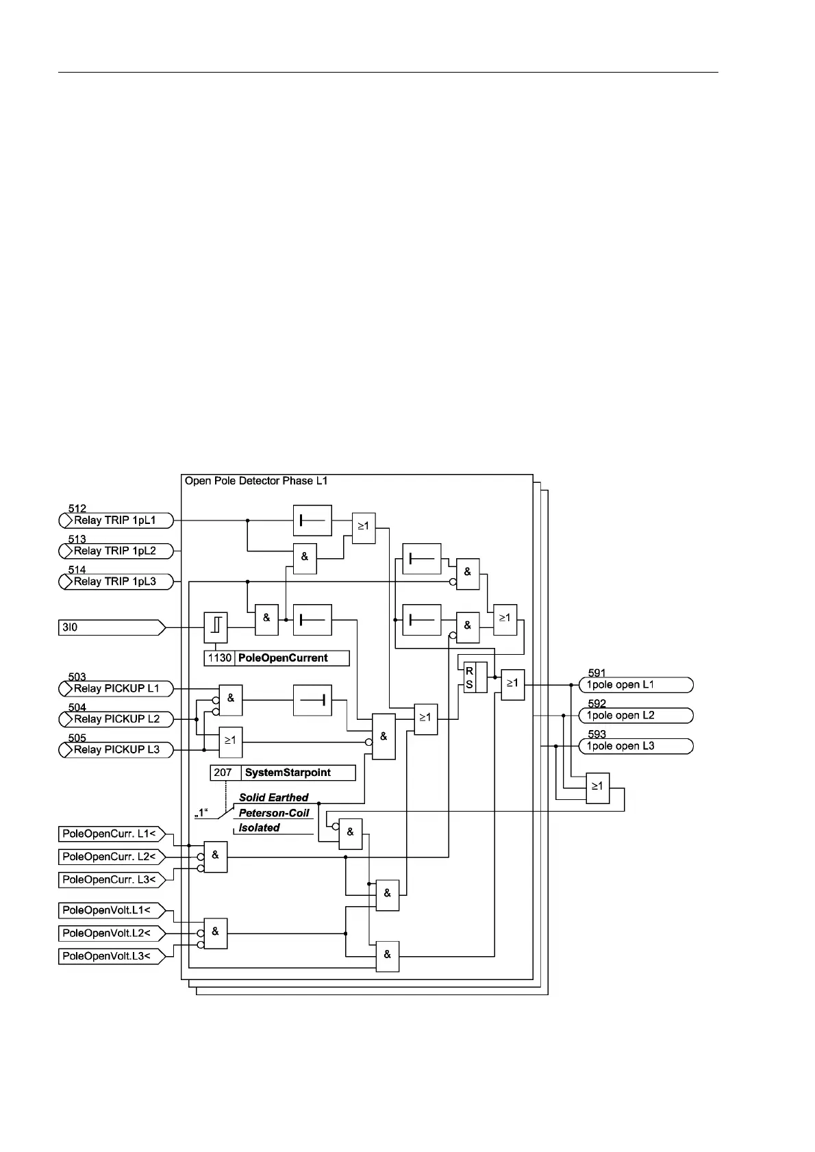
2.20.1.3 Open Pole Detector
Single-pole dead times can be detected and reported via the Open Pole Detector. The
corresponding protection and monitoring functions can respond. The following figure
shows the logic structure of an Open Pole Detector.
Figure 2-152 Open pole detector logic

 Loading...


