3.1 Mounting and Connections
383
7SA522 Manual
C53000-G1176-C155-3
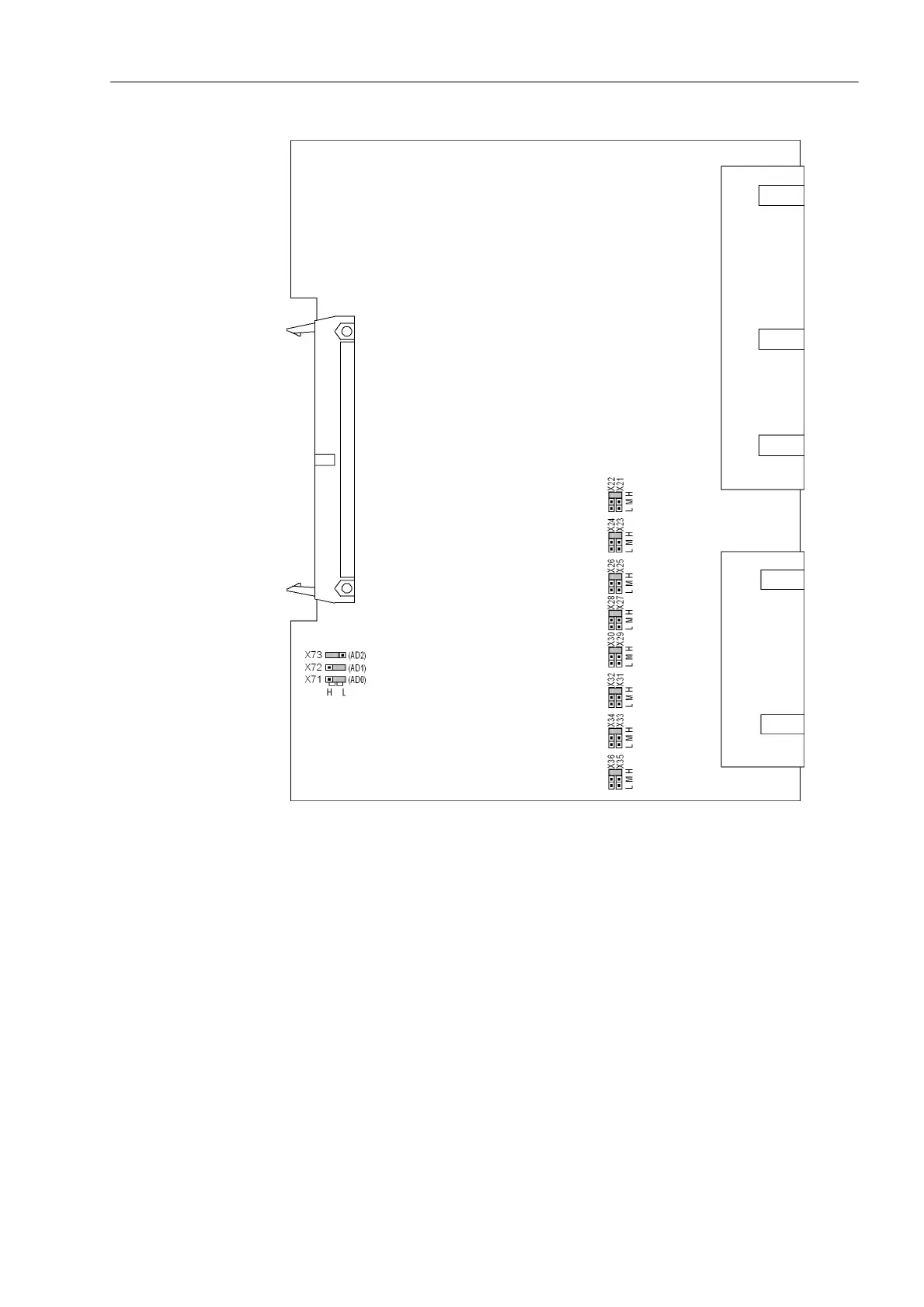
Figure 3-6 Input/output board C–I/O-10 with representation of the jumper settings required
for the board configuration
Check of the control voltages of the binary inputs:
BI1 to BI8 (with housing size
1
/
2
) according to Table 3-5.
BI1 to BI24 (with housing size
1
/
1
depending on the version) according to Table 3-6.

 Loading...


