4 Technical Data
438
7SA522 Manual
C53000-G1176-C155-3
Time Synchronization Interface
DNP3.0/RS485
Connection for panel flush mounting
housing
Rear panel; mounting location “B”;
9-pin D-subminiature female connector
Connection for panel surface mounting
housing
In console housing
Test voltage 500 V; 50 Hz
Transmission speed Up to 19200 Baud
Transmission distance Max. 1 km
DNP3.0/Optical Fibre
FO connector type ST–Connector Receiver/Transmitter
Connection for panel flush mounting
housing
Rear panel, mounting location “B”
Connection for panel surface mounting
housing
In console housing
Transmission speed Up to 19200 Baud
Optical wavelength λ = 820 nm
Laser Class 1 according to EN60825-1/-2 Using glass fibre 50/125 µm or
Using glass fibre 62.5/125 µm
Permissible optical signal attenuation Max. 8 dB, with glass fibre 62.5/125 µm
Transmission distance Max. 1.5 km
1)
If the optical interface is required you shall order the following: 11th position 4 (FMS) or L0A (DP) and additionally:
For single ring: SIEMENS OLM 6GK1502-3AB10, for double ring: SIEMENS OLM 6GK1502-4AB10
The OLM converter requires an operating voltage of 24 VDC. If the operating voltage is > 24 VDC the additional power
supply 7XV5810-0BA00 is required.
Time synchronisation DCF 77/IRIG B-Signal (telegram format IRIG-B000)
Connection for panel flush mounting housing Rear panel, slot “A”
9-pin D-subminiature female connector
Connection for panel surface mounting housing At the double-deck terminal on the case bottom
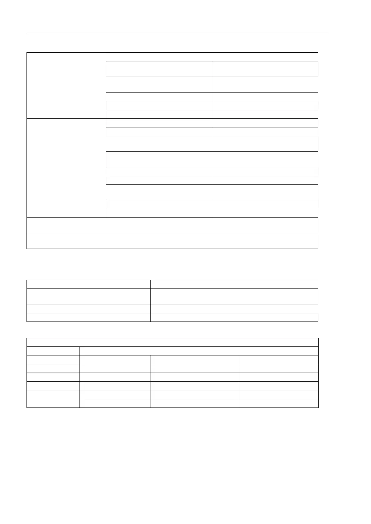
Signal nominal voltages Selectable 5 V, 12 V or 24 V
Signal Levels and Burdens:
Nominal Signal Voltage
5 V 12 V 24 V
V
IHigh
6.0 V 15.8 V 31 V
V
ILow
1.0 V at I
ILow
= 0.25 mA 1.4 V at I
ILow
= 0.25 mA 1.9 V at I
ILow
= 0.25 mA
I
IHigh
4.5 mA to 9.4 mA 4.5 mA to 9.3 mA 4.5 mA to 8.7 mA
R
I
890 Ω at U
I
= 4 V 1930 Ω at U
I
= 8.7 V 3780 Ω at U
I
= 17 V
640 Ω at U
I
= 6 V 1700 Ω at U
I
= 15.8 V 3560 Ω at U
I
= 31 V

 Loading...


