4 Technical Data
452
7SA522 Manual
C53000-G1176-C155-3
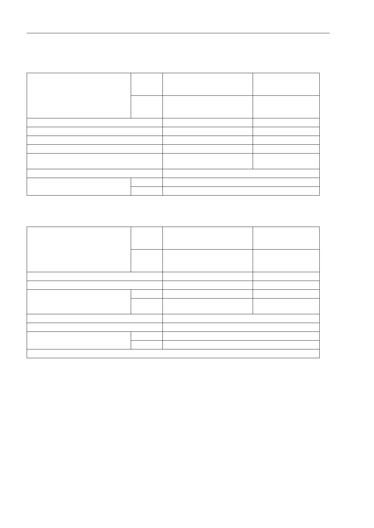
Inverse Time Overcurrent Stage with Logarithmic-inverse Characteristic
Zero Sequence Voltage Time Protection Stage (U0-inverse)
Pickup value 3I
0P
for I
N
= 1 A 0.05 A to 25.00 A
or
0.003 A to 25.000 A
Increments 0.01 A
Increments 0.001 A
for I
N
= 5 A 0.25 A to 125.00 A
or
0.015 A to 125.000 A
Increments 0.01 A
Increments 0.001 A
Pickup value 3I
0P FACTOR
1.0 to 4.0 Increments 0.1
Time factor T
3I0P
0.05 s to 15.00 s; ∞ Increments 0.01 s
Maximum time T
3I0P max
0.00 s to 30.00 s Increments 0.01 s
Minimum time T
3I0P min
0.00 s to 30.00 s Increments 0.01 s
Additional time delay T
3I0P verz
0.00 s to 30.00 s
or ∞ (ineffective)
Increments 0.01 s
Characteristics See Figure 4-4
Tolerances
Times
inv. 5 % ± 15 ms for 2 ≤ I/3I
0P
≤ 20 and T
3I0P
/s ≥ 1
def. 1 % of setting value or 10 ms
Pickup value 3I
0P
for I
N
= 1 A 0.05 A to 25.00 A
or
0.003 A to 25.000 A
Increments 0.01 A
Increments 0.001 A
for I
N
= 5 A 0.25 A to 125.00 A
or
0.015 A to 125.000 A
Increments 0.01 A
Increments 0.001 A
Pickup value 3U
0
> 1.0 V to 10.0 V Increments 0.1 V
Voltage factor U
0 inv. minimal
0.1 V to 5.0 V Increments 0.1 V
Additional time delay T
directional
0.00 s to 32.00 s Increments 0.01 s
T
non-direction-
al
0.00 s to 32.00 s Increments 0.01 s
Characteristics See Figure 4-5
Tolerances times 1 % of setting value or 10 ms
Dropout ratio Current Approx. 0.95 for I/I
N
≥ 0.5
Voltage Approx. 0.95 for 3U
0
≥ 1V
The set times are pure delay times

 Loading...


