2.1 General
51
7SA522 Manual
C53000-G1176-C155-3
Where
Z
0
= (complex) zero sequence impedance of the line
Z
1
= (complex) positive sequence impedance of the line
These values may either apply to the entire line length or be based on a per unit of line
length, as the quotients are independent of length. Furthermore it makes no difference
if the quotients are calculated with primary or secondary values.
For overhead lines it is generally possible to calculate with scalar quantities as the
angle of the zero sequence and positive sequence system only differ by an insignifi-
cant amount. With cables however, significant angle differences may exist as illustrat-
ed by the following example.
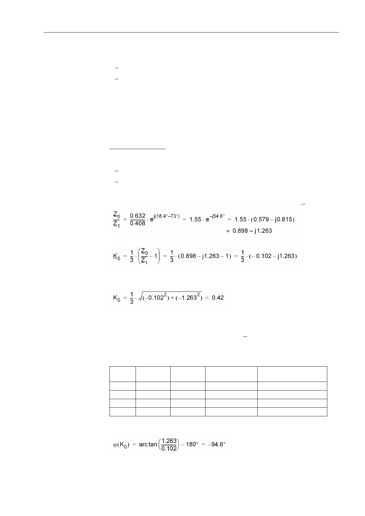
Calculation Example
:
110 kV single-conductor oil-filled cable 3 · 185 mm
2
Cu with the following data
Z
1
/s = 0.408 · e
j73°
Ω/km positive sequence impedance
Z
0
/s = 0.632 · e
j18.4°
Ω/km zero sequence impedance
(where s = line length)
The calculation of the earth impedance (residual) compensation factor K
0
results in:
The magnitude of K
0
is therefore
When determining the angle, the quadrant of the result must be considered. The fol-
lowing table indicates the quadrant and range of the angle which is determined by the
signs of the calculated real and imaginary part of K
0
.
Table 2-1 Quadrants and ranges of the angle K
0
In this example the following result is obtained:
Real part Imaginary
part
tan ϕ(K0) Quadrant/range Calculation
+ + + I 0° ... +90° arc tan (|Im| / |Re|)
+ – – IV –90° ... 0° –arc tan (|Im| / |Re|)
– – + III –90° ... –180° arc tan (|Im| / |Re|) –180°
– + – II +90° ... +180° –arc tan (|Im| / |Re|) +180°

 Loading...


