2 Functions
88
7SA522 Manual
C53000-G1176-C155-3
Most important for this setting on overhead lines, is the resistance of the fault arc. In
cables on the other hand, an appreciable arc can not exist. On very short cables, care
must however be taken that an arc fault on the local cable termination is inside the set
resistance of the first zone.
The resistance of the line itself does not have to be considered since it is accounted
for through the shape of the polygon provided that the line angle is at least as large as
the inclination angle 'LVWDQFH$QJOH (address ) of the polygon.
Example
:
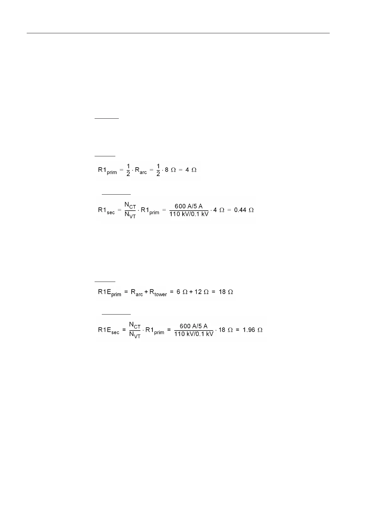
A maximum arc voltage of 8kV is assumed for phase–phase faults (line data as
above). If the minimum primary short-circuit current is assumed to be 1000 A this cor-
responds to 8 Ω primary. For the resistance setting of the first zone this implies
primary
:
or secondary
:
Only half the arc resistance was applied in the equation, as it is added to the loop im-
pedance and therefore only half the arc resistance appears in the per phase imped-
ance.
A separate resistance tolerance can be set for earth faults. An arc resistance of 6 Ω
and a tower footing resistance of 12 Ω is assumed. This results in the following
primary
:
or secondary
:
In this case the least favourable condition was assumed, whereby the earth current
does not return via the measuring point. If all the earth current, or a portion of the earth
current flows via the measuring point, the measured resistance decreases. When
there is an infeed from the remote end, the measured resistance may be increased.
Independent Zones
Z1 up to Z5
By means of the parameter MODE = )RUZDUG or 5HYHUVH or 1RQ'LUHFWLRQDO
each zone can be set (address 2SPRGH=, 2SPRGH=, 2S
PRGH=, 2SPRGH= and 2SPRGH=). This allows any combina-
tion of reverse, forward, or non-directional graded zones, for example on transformers,
generators or bus couplers. In the fifth zone different reach in the X direction can be
set for forward or reverse. Zones that are not required are set ,QDFWLYH.
The values derived from the grading coordination chart are set for each of the required
zones. The setting parameters are grouped for each zone. For the first zone these are
the parameters 5= (address ) for the R intersection of the polygon ap-
plicable to phase-phase faults, ;= (address ) for the X intersection (reach),

 Loading...


