Description, device design, dimension drawing
2.6 Connections and terminal designations
Power supply system SITOP PSU8600
36 Manual, 09.2018, A5E36758446-5-76
The power cables to the battery module are connected at power terminals ③. The data
cables are connected at communication terminals
④.
It is not permissible that the "+" and "-" power terminals are connected to the "0V", the 0V
busbar or "GROUND".
Using control contact "ON" ⑤, the buffer readiness of the UPS module can be activated and
deactivated – and/or an active buffer mode exited. When the power supply voltage is
missing, the power supply system can be directly started from the energy storage device
(island operation) using control contact "START"
⑥.
Using signaling contact "READY"
⑦, it can be interrogated as to whether the buffer module
has reached an adequate charge state. Using signaling contact "BUF"
⑧, the system
signals that it is currently in the buffer mode. Disturbance-free operation of the connected
battery module is signaled using signaling contact "OK"
⑨.
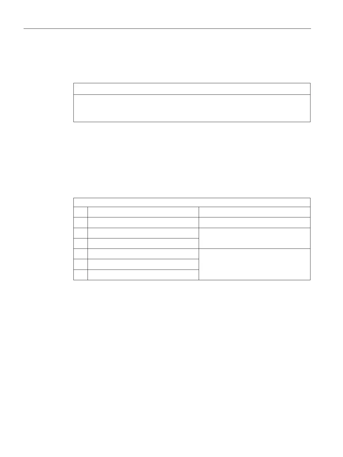
Connections and terminal designations
"+" and "-" power terminals Plug-in terminal each with a screw connection
Communication terminals
COM1
, "COM2" Plug-in terminal each with a screw connection
Control contact "ON"
,
Common plug-in terminal each with a screw
connection
Control contact "START"
,
Signaling contact "READY"
,
Common plug-in terminal each with a screw
connection
Signaling contact "BUF"
,
"OK" signaling contact
,
See the diagram in Section "Description of the UPS module (Page 26)".

 Loading...


