Description, device design, dimension drawing
2.9 Signaling contacts/control contacts
Power supply system SITOP PSU8600
Manual, 09.2018, A5E36758446-5-76
61
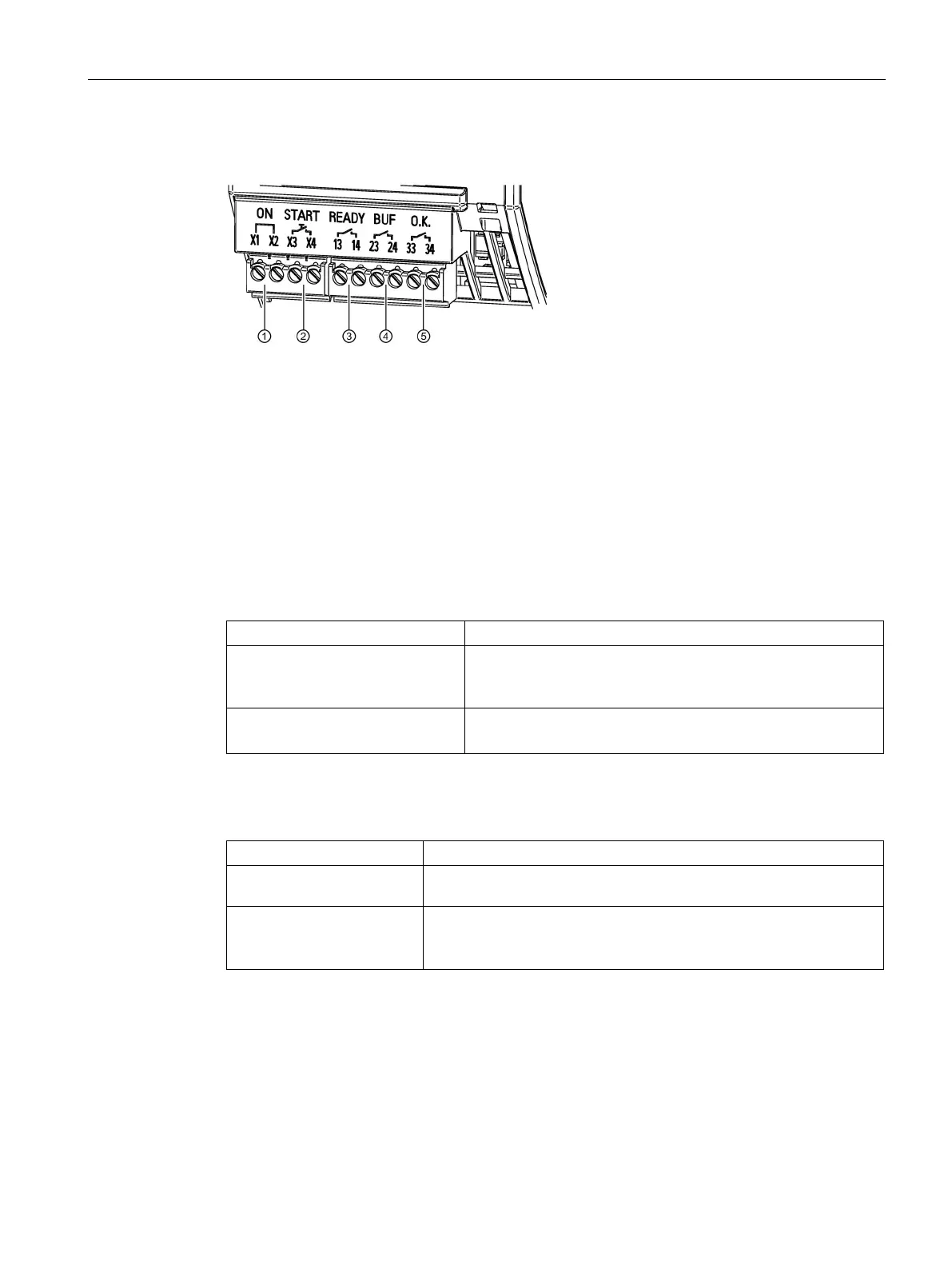
"READY" signaling contact
Using control contact "ON" (terminals "X1" and "X2",
①), the buffer mode of the UPS
module can be deactivated if the power supply (line voltage) is scheduled to be shut down
(e.g. maintenance, pause, end of work/end of shift). This avoids unnecessarily discharging
the battery module.
Deactivation via the control contact is effective for all of the buffer components in the system.
X1-X2 closed
< 10 Ω
(Delivery state: via wire jumper)
Buffer mode of the UPS module enabled.
System is buffered when the power fails.
X1-X2 open
> 1 MΩ
All of the buffer components in the system deactivated.
The system is not buffered when the power fails.
Using control contact "START" (terminals "X3" and "X4", ②), when the power supply voltage
(line voltage) is missing, the power supply system can be started using the energy saved in
the battery module (island operation).
X3-X4 closed
The power supply system is started from the battery module.
X1-X2 open
> 1 MΩ
Starting from the battery module deactivated.
The signaling contact sufficient buffer readiness "READY" is in the form of a relay contact
(NO contact, terminals "13" and "14",
③) - and signals that the buffer module is charged to x
% (factory setting: 85 %) and is therefore ready for buffering. The threshold value can be
freely parameterized via the Industrial Ethernet/PROFINET interface.

 Loading...


