B-4
4. Disconnect connectors P9 and P10, located on the left side of the panel’s
PC board. Label the wires to make reattachment easier. See Figure B-2.
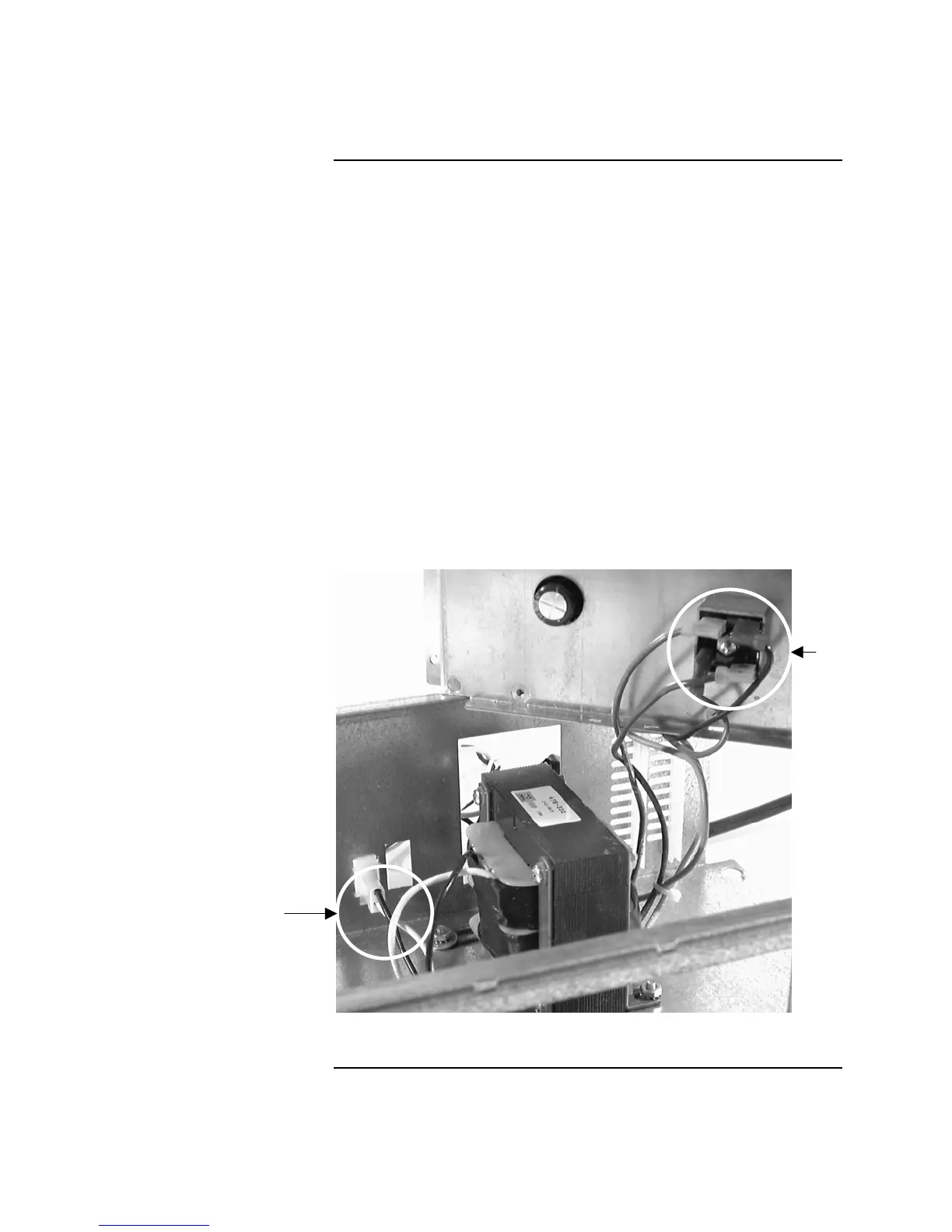
5. Lift the panel’s electronics from the chassis, and visually inspect the four
connectors attached to the bridge rectifier. See Figure B-3. Remove each
connector one at a time and check the crimped connection between the
connector and the wire. Gently pull on the wires to make sure that they are
firmly attached to the connector.
6. Remove and visually inspect the AC power bulkhead connector. This
connector mounts to the bottom of the panel chassis, and connects the
incoming AC Power wiring to the input wiring of the line voltage
transformer. Check the crimped connection between the connector and the
wires. Gently pull on the wires to make sure that they are firmly attached to
the connector. Refer to Figure B-3 for the location of the bulkhead
connector.
7. Reattach all connectors and reapply AC power. If the green LED still does
not light, replace the transformer and bridge rectifier. Refer to “Replacing
the Line Voltage Transformer and Bridge Rectifier” later in this section for
information on doing this.
Figure B-3. Visually Inspect the Condition of Terminals
Continued on next page
Checking AC Power Supply Transformer / Bridge Rectifier, Continued
Checking Connectors
(continued)
Bridge
Rectifier
AC Power
Bulkhead
Connector
Technical Manuals Online! - http://www.tech-man.com