B-5
If there is no voltage at H1 and H2 and a visual inspection of the connectors
does not reveal any obvious problems, you should replace the line voltage
transformer and the bridge rectifier, using the following instructions.
1. REMOVE AC POWER FROM THE PANEL.
2. Remove the four Torx screws that secure the panel’s electronics to the
chassis.
3. Disconnect the External Power Supply harness from connectors P13 and
P14 on the 4010 PC board.
4. Disconnect connectors P9 and P10, located on the left side of the panel’s
PC board. Label the wires to make reattachment easier. See Figure B-3.
5. Lift the panel’s electronics from the chassis, and disconnect the four
connectors attached to the bridge rectifier.
6. Unbolt the bridge rectifier and transformer from the 4010 chassis and
replace.
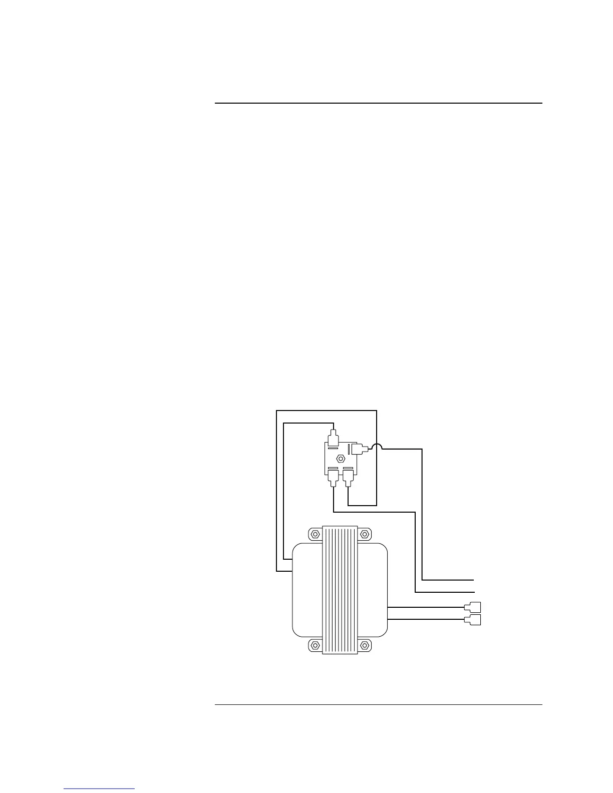
7. Reattach all wiring as shown in Figure B-4.
8. Reconnect all connectors and reapply AC Power.
ORG
YEL
RED
TRANSFORMER
BLK
BLU
BRN
BRIDGE
RECTIFIER
AC
AC-
+
Figure B-4. AC Transformer Bridge Rectifier Wiring
Checking AC Power Supply Transformer / Bridge Rectifier, Continued
Replacing the Line Voltage
Transformer and Bridge
Rectifier
P9
P10
H1
H2
Technical Manuals Online! - http://www.tech-man.com