B-2
The AC Power Supply Brownout Potentiometer (R252) is factory adjusted and
should not require field adjustment. The exception to this is when an SFIO
board is received in the field without a BIN file downloaded to it. This indicates
that the board may not have been factory adjusted and tested. In this case, you
should download a BIN file to the SFIO and adjust the brownout. This allows
you to use the system until a new SFIO board can be ordered and installed.
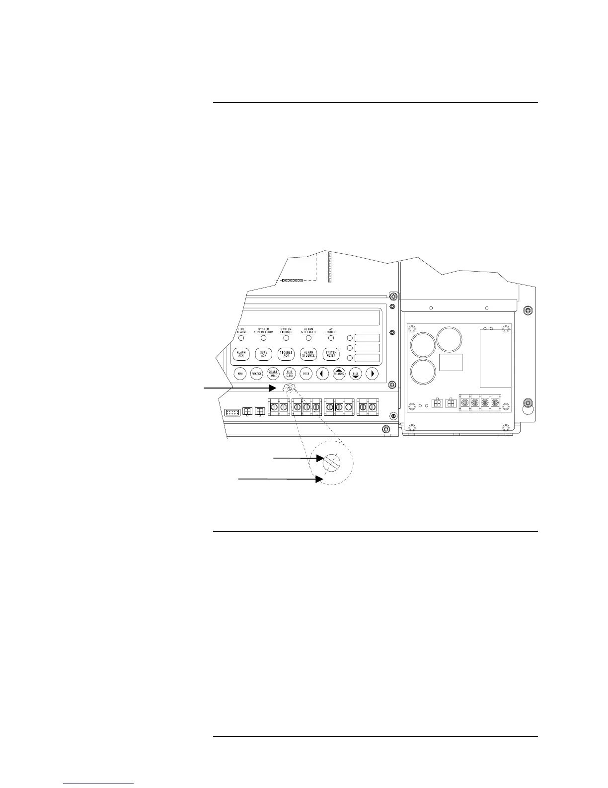
Figure B-1 shows the proper position for this potentiometer. The slot on the
potentiometer should be positioned such that an imaginary, perpendicular line
extends from the middle of the slot to the 1:00 position. In Figure B-1, the
dashed line represents this imaginary line.
+
2
-
1
+ - + -
12
1
2
3
Figure B-1. Correct Position AC Power Supply Brownout
Potentiometer
The following procedure describes using a variac to adjust the brownout circuit.
The brownout potentiometer is R252, which is located just above the AUX
PWR terminal strip and just below the Exit/Clear button. Remove the LCD
display prior to performing this adjustment.
1. Turn R252 counter-clockwise to its maximum resistance setting.
2. Connect the system to nominal AC line voltage.
3. Adjust the AC input voltage to place the system in brownout.
4. Adjust the AC input voltage to 107.8 – 108 VAC.
5. Adjust R252 until K8 energizes.
As adjusted above, a lightly loaded system (no alarm current – just normal
standby) will not transfer to batteries until about 80 VAC. It will return at the
same point under load or not load. When returning from brownout, the system
may take up to 30 seconds after the voltage has stabilized at 107.8 –108 VAC
before switching from batteries to AC line voltage.
Adjusting the AC Power Supply Brownout Potentiometer
Overview
Using a Variac to Adjust the
Brownout Potentiometer
Screw Slot
Imaginary Line
R252
Technical Manuals Online! - http://www.tech-man.com