B-6
If the initial troubleshooting indicates that the EPS is receiving adequate 120
VAC from the AC circuit, the next step is to verify the integrity of the EPS
transformer, bridge rectifier, and their connectors.
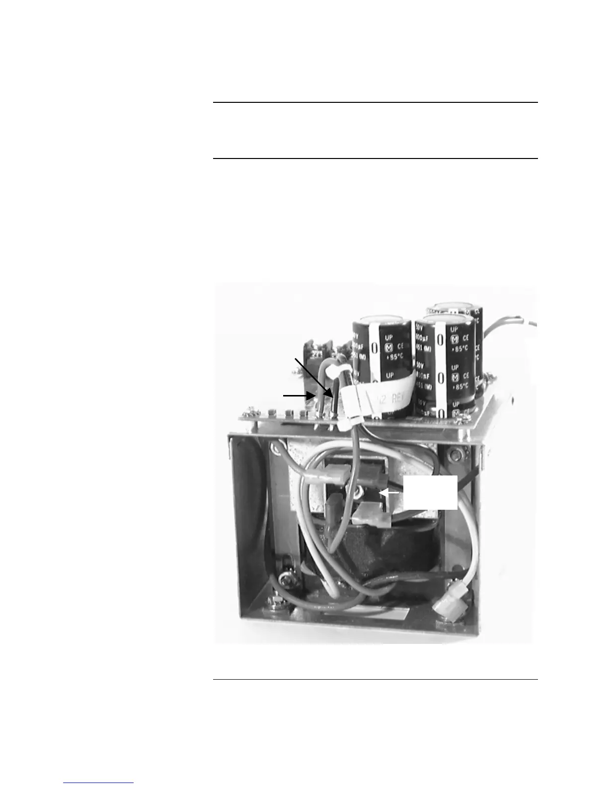
1. Meter the DC voltage across the terminals marked RED1 and BLK1 on the
EPS. Meter the terminals at the crimp, just at the point where the wires
attach to the PC board. Refer to Figure B-5. These terminals connect to the
bridge rectifier mounted on the rear of the EPS, which in turn connects to
the EPS line voltage transformer. DC Voltage across these terminals should
be within the range of 21-32 VDC.
2. If there is no power at RED1 and BLK1, there may be a problem with the
EPS line voltage transformer, bridge rectifier, or one of the connectors.
Figure B-5. Location of RED1 and BLK1
Continued on next page
Checking EPS Transformer / Bridge Rectifier
Introduction
Checking DC Voltage from
EPS Bridge Rectifer
RED1
BLK1
Bridge
Rectifier
Technical Manuals Online! - http://www.tech-man.com