B-7
A series of plastic connectors link the EPS’s line voltage transformer and bridge
rectifier to the building’s AC power circuit. Checking the integrity of these
connectors allows you to eliminate these components as a possible cause for
EPS power problems.
1. REMOVE POWER (AC and Battery) FROM THE PANEL.
2. Remove the two Torx screws that secure the EPS to the chassis.
3. Disconnect the EPS harness from connectors P1 and P2 on the EPS module.
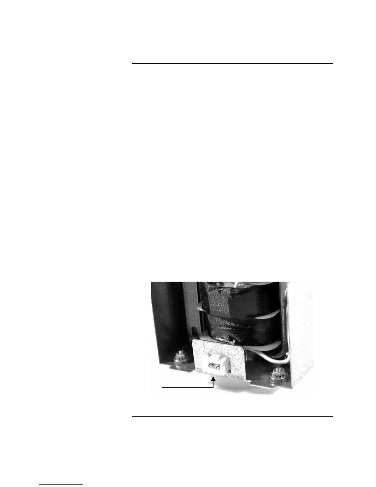
4. Disconnect and visually inspect the AC power connector on the side of the
EPS. This connector mounts to the bottom of the panel chassis, and
connects the incoming AC Power wiring to the input wiring of the EPS line
voltage transformer. Disconnect and check the connectors and wires.
Gently pull on the wires to make sure that they are firmly attached to the
connector. Refer to Figure B-6 for the location of the bulkhead connector.
5. Lift the EPS assembly from the chassis, and visually inspect the four
connectors attached to the bridge rectifier. See Figure B-5 for their
location. Remove each connector one at a time and check the crimped
connection between the connector and the wire. Gently pull on the wires to
make sure that they are firmly attached to the connector.
6. Reattach all connectors and reapply AC power. Check the voltage at RED1
and BLK1. If there still is no voltage, replace the EPS’s line voltage
transformer and bridge rectifier. Refer to “Replacing the EPS Line Voltage
Transformer and Bridge Rectifier” later in this chapter for information on
doing this.
Figure B-6. Visually Inspect the Condition of Terminals
Continued on next page
Checking EPS Transformer / Bridge Rectifier, Continued
Checking Connectors
EPS
Bulkhead
Connector
Technical Manuals Online! - http://www.tech-man.com