D-2
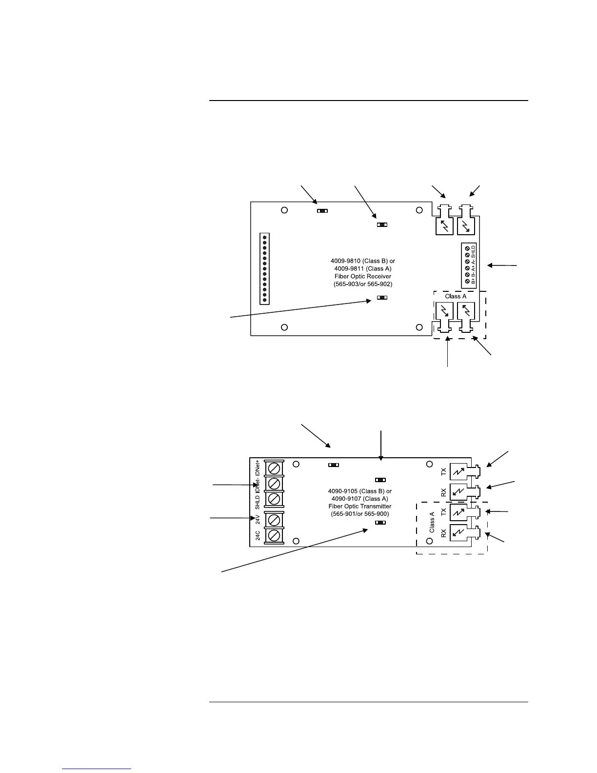
Figure D-1 shows the locations of the connectors and LEDs for the 4009 IDNet
Fiber Optic cards, which can be used to link the 4010 to a remote 4009 IDNet
NAC extender.
FIBER RECEIVER CARD
FIBER TRANSMITTER CARD
Figure D-1. 4009 IDNet Fiber Receiver/IDNet Transmitter Option
Cards
Overview
Introduction
FIBER TRANSMIT
LED2
(SEE NOTE 1)
FIBER TRANSMIT
LED1
(SEE NOTE 1)
CLASS A FIBER TRANSMIT
LED3
(SEE NOTE 1)
POWER TERMINAL BLOCK
TB2
IDNet TERMINAL BLOCK
TB2
FIBER OPTIC
TRANSMITTER
U19
FIBER OPTIC
RECEIVER
U20
FIBER OPTIC
TRANSMITTER
U21
(SEE NOTE 2)
FIBER OPTIC
RECEIVER
U22
(SEE NOTE 2)
Notes:
1. LEDs 1-3 indicate the following conditions:
• Green LED1 flashes when data is being transmitted out fiber.
• Red LED2 flashes when data is being received from fiber.
• Red LED3 flashes when data is being received on the Class A fiber receiver.
2. Shown equipped with optional Class A Receiver/Transmitter Card components.
IDNet INTERFACE
TB1
FIBER TRANSMIT
LED1
FIBER RECEIVE
LED2
CLASS A FIBER RECEIVE
LED3
FIBER OPTIC
TRANSMITTER
U16
FIBER OPTIC
RECEIVER
U18
FIBER OPTIC TRANSMITTER
U17
FIBER OPTIC RECEIVER
U19
Technical Manuals Online! - http://www.tech-man.com