2-14
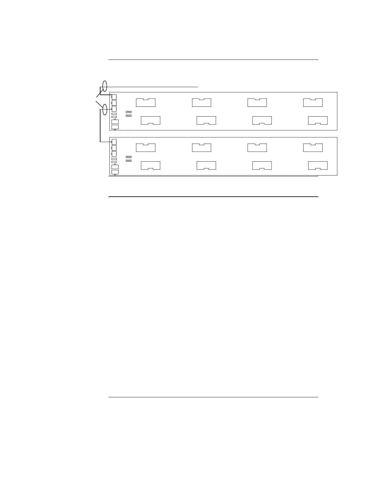
Figure 2-8, below, shows the interconnections between three bays in a host panel.
4100 POWER DISTRIBUTION INTERFACE
ASSY 566-084
4100 POWER DISTRIBUTION INTERFACE
ASSY 566-084
Figure 2-8. Bay-to-Bay Interconnections
Panels with motherboards on the left side of the expansion bays require some non-PDI
connections. If you need to connect a harness to a motherboard, refer to Figure 2-9 and
follow these steps. Make sure to route the power and communication wiring on the left
side of the bay.
1. Connect one end of the 733-525 Harness to a motherboard in an adjacent bay.
If the adjacent bay is a CPU bay with no additional motherboards, connect the
harness to the P8 and P7 connectors of the CPU motherboard:
Insert the harness connector with the blue wire into the P8 connector. Note that
the P8 connector has eight pins. Insert the harness connector on either the top
four pins or the bottom four pins, not in the middle.
Insert the harness connector with the white wire into the P7 connector. Note that
the P7 connector has eight pins. Insert the harness connector on either the top
four pins or the bottom four pins, not in the middle.
If the adjacent bay is an expansion bay or a CPU bay with additional motherboards,
connect the harness to the P2 and P3 connectors of the motherboard installed in the
leftmost slot. Connect the harness as follows:
Insert the harness connector with the blue wire into the P2 connector. Note that
the P2 connector has eight pins. Insert the harness connector on either the top
four pins or the bottom four pins, not in the middle.
Insert the harness connector with the white wire into the P3 connector. Note that
the P3 connector has eight pins. Insert the harness connector on either the top
four pins or the bottom four pins, not in the middle.
Continued on next page
Step 4. Interconnecting Modules and Bays, Continued
Basic Bay-To-Bay
Interconnections
(continued)
Connecting to
Motherboards
HARNESS
734-008
From Previous PDI, SPS or master motherboard
P1
P2
P3
P4
P5
P6
P7
P1
P2
P3
P4
P5
P6
P7