11 Transaxle Removal & Installation
Transaxle Removal – All Models
11 - 2
WARNING
Before beginning any service work, turn the PTO
off, set the parking brake, turn the ignition switch
off, and remove the key. Disconnect the spark
plug wire(s) on gas engine models, and discon-
nect the negative battery cable.
TRANSAXLE REMOVAL AND
INSTALLATION
General
Removal of the transaxle assembly is accomplished by
disconnecting all control linkages, hydraulic lines and
hoses, drive shaft and mounting hardware, and pulling
the assembly from the rear of the tractor. Installation is
the reverse of this procedure.
Transaxle Removal – All Models
1. Remove the seat deck assembly (refer to Section 15,
SEAT & SEAT DECK SERVICE).
2. Remove the foot rest assembly (refer to Section 14,
HOOD, DASH & FOOT REST SERVICE).
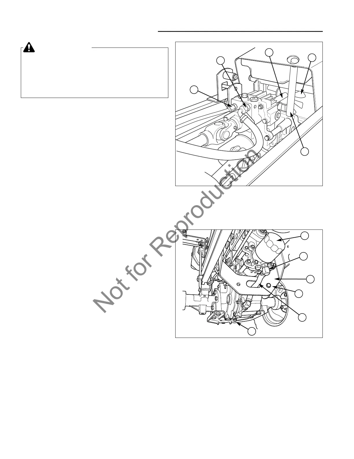
3. With the seat deck and foot rest assemblies
removed, remove the hydraulic pressure hose (A,
Figure 1) on the top right side of the hydrostatic unit.
Cap the fitting on the pump and plug the line to pre-
vent hydrostatic oil contamination.
4. Remove the hydraulic return line elbow (B) on the top
left side of the hydrostatic unit. Cap the fitting on the
pump and plug the elbow to prevent contamination of
the hydrostatic oil in the system.
5. Remove the hydraulic system fill tube (C), and plug
the hole in the top of the transaxle to prevent
hydraulic system contamination.
6. Remove the hydrostatic pump fan shaft (D) with fan
(E) on the rear of the housing.
7. Drain the Hydrostatic Unit into a suitable container by
removing the 3/8" pipe plug (A, Figure 2) from the
bottom right side of the housing. Replace and tighten
the 3/8" pipe plug (A). Remove the oil filter (B).
8. Remove the preformed drain hose (C) from the elbow
fitting (D) on the bottom of the housing, and remove
the elbow. Plug the fitting port in the housing and the
drain hose (C) to prevent contamination from entering
the system.
Figure 1. Component Removal – Upper
A. Hydraulic Pressure Line D. Fan Drive Shaft
B. Hydraulic Return Line E. Fan Blade
C. Hydraulic System Fill Tube
D
E
A
C
B
Figure 2. Component Removal – Lower
A. Drain Plug D. Drain Elbow
B. Hydraulic Oil Filter E. Transaxle Mounting Bolt
C. Drain Hose F. Frame Crossmember
B
D
F
E
C
A