11 - 3
11 Transaxle Removal & Installation
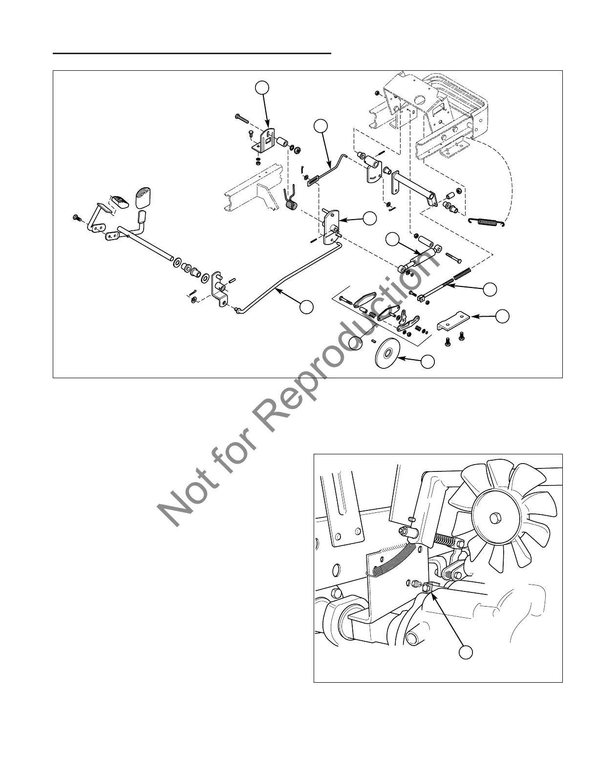
Transaxle Removal – All Models
9. Remove the pedal to lever direction control rod (A,
Figure 3) and cruise to lever assembly control rod (B)
from the control lever assembly (C) on the right side
of the hydrostatic housing (Refer to Section 9, DRIVE
CONTROLS for additional information if required).
10. Remove the hardware securing the pedal stop plate
assembly (D) on the top of the right frame member,
and remove the pedal stop plate assembly.
11. Remove the hardware securing the shock absorber
(E) to the frame and control lever assembly (C) on
the right side of the hydrostatic housing, and remove
the shock absorber.
12. Remove the hardware securing the differential lock
cable clevis (A, Figure 4) to the control rod on the left
side of the transaxle.
13. Remove the hardware securing the brake rod
(F, Figure 3) to the caliper assembly (H) on the left
side of the transaxle, and remove the rod. Remove
the hardware securing the brake caliper mounting
bracket (G) to the frame member, and remove the
caliper assembly (H) from the brake disc (I).
Figure 3. Linkage Removal
A. Pedal Direction Control Rod D. Pedal Stop Plate Assembly G. Mounting Bracket
B. Cruise Assembly Control Rod E. Shock Absorber H. Caliper (Exploded)
C. Control Lever Assembly F. Brake Rod I. Brake Disc
A
D
B
C
E
Figure 4. Differential Lock Cable Removal
A. Cable Clevis
A
F
G
I
H