D10 D11 D12 D13 Status Possible
reasons
any any any steady The fatal
problem was
found by the
main
software. The
system will
be restarted.
An
unexpected
error occurs
After turning on the board, LEDs D11 and D12 should be blinking within a few seconds. This
indicates the system is working properly.
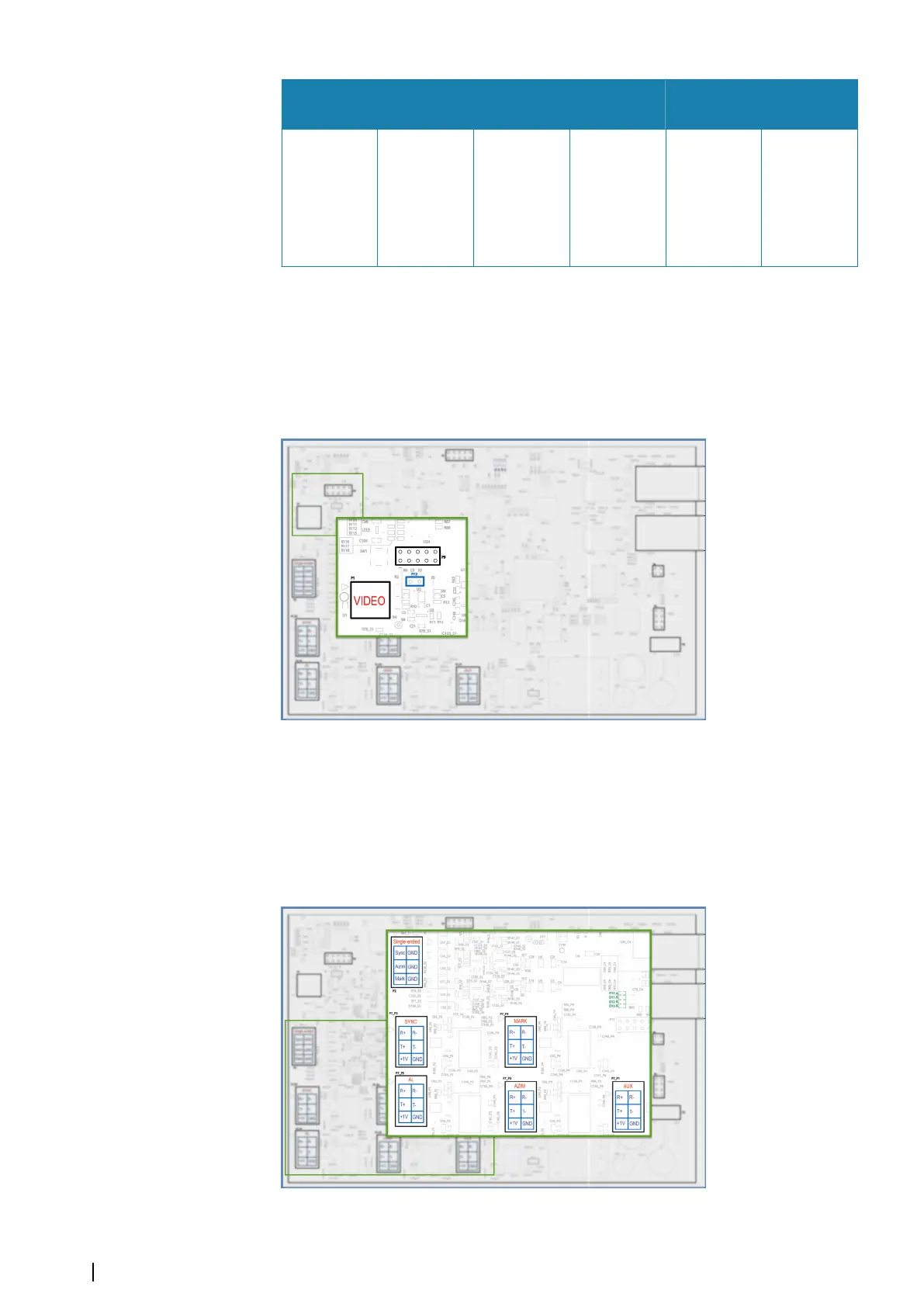
The radar video signal
By default, video input impedance is 75 Ohm. If 50 Ohm is required, set the jumper P12. This
is the only jumper which can be used by the customer. All other jumpers are for Navico. By
default, there is no jumper.
Synchronization signals
The following connection types are available:
• Single-ended
• Differential
• Composite
Depending on the connection type, different connectors are used. The MK 6.0 Radar
Interface box board layout is represented below.
There are 6 connectors on the board:
10
Connections | MK 6.0 Installation Manual