Single-ended connection using the differential connectors
Differential connectors are galvanic isolated from the board so they can be used for
connecting lines with different grounds. The signal must be within the -7V to +12V limit. The
triggering level is 1 V and cannot be changed. The system will work correctly only if the pulse
crosses the 1 V level and the noise is lower.
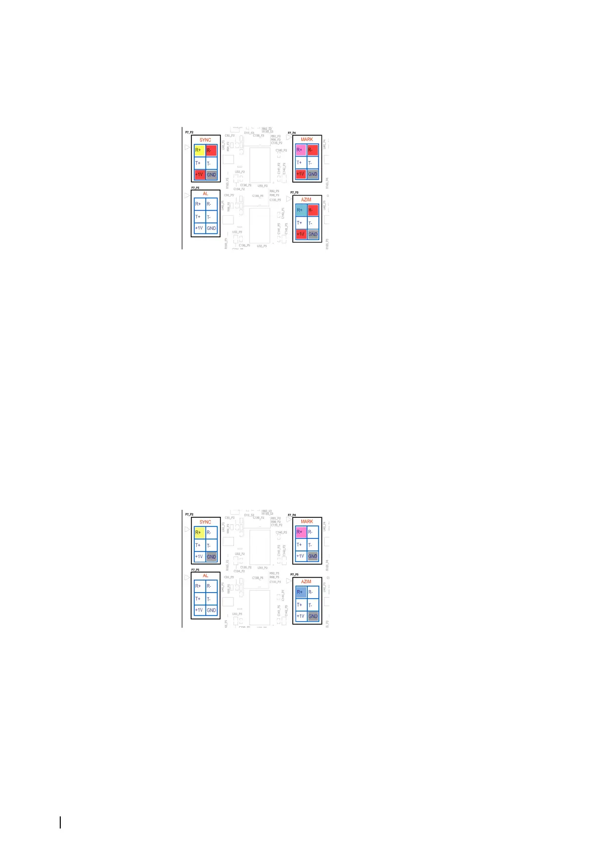
The single-ended connection using the differential connectors
The following color coding is used for wires:
• Grey - Ground
• Yellow - Sync
• Blue - Azimuth
• Magenta - Mark
• Red - short-cirquit contact between pins of the same connector.
Differential synchronization signals
The following connectors are used for differential synchronization lines:
• SYNC
• AZIM
• MARK
The following color coding is used foe wires:
• Yellow - Sync
• Grey - Ground
• Blue - Azimuth
• Magenta - Mark
The signal must be within the +7V to +12V limit.
The different synchronization signal connection scheme.
Litton/Sperry synchronization signals
In this case the MK 6.0 Radar Interface box can be connected as Master. In addition to the
input signals from the radar, the device produces output control signals.
The SYNC and AL connectors should be used for connecting synchronization signals from
Litton/Sperry radar to the MK 6.0 Radar Interface box board.
The following order is correct:
• Sync signals to the SYNC connector, R+ and R- pins
• Azimuth signals to the AL connector, R+ and R- pins
• Radar control signals to the AL connector, T+ and T- pins
12
Connections | MK 6.0 Installation Manual