Selecting the “100 Ohm pull down” check box connects the corresponding single ended
input to the ground using a 100 Ohm resistor. This resistor can be used for impedance
matching.
Selecting the “430 Ohm pull up” check box connects the corresponding single ended input
to +3.3V. This resistor can be used for connecting to radars with open collector outputs.
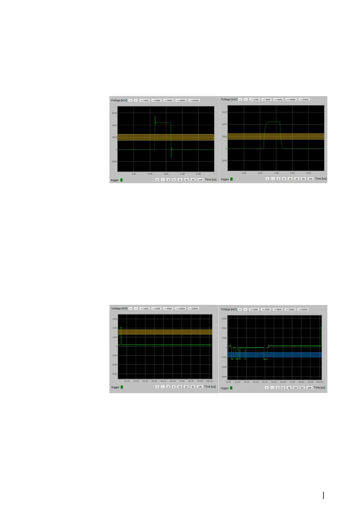
Selecting the “1000 pF filter” check box for Sync, Azimuth and Marker connects the1000 pF
capacitor to the corresponding input. This capacitor can be used as a filter. Influence of the
capacitor on the Sync signal is shown in the figure below.
The example of a capacitor influence on the Sync signal
Composite synchronization signals
The MK 6.0 Radar Interface box can work with two composite radars: Raytheon and Atlas. For
both radars, the synchronization signals are mixed with the video signal but these two radars
use different coding. For composite signals, besides the signal trend, the oscilloscope shows
the triggering level (yellow line for Sync, blue for Azimuth and magenta for Marker). For
stability of the synchronization, the board uses hysteresis. The thickness of the line
corresponds to the value of the hysteresis. For composite signals the hysteresis is 0.5 Volt.
Trigger levels must be set differently for Raytheon and Atlas.
Position of Sync (yellow line) and Azimuth (blue line) triggers are shown in the figure below.
The Sync level should be on the top of the Sync signal to be higher than the video signal
(there is no video on the picture because it was taken using a simulator). The Azimuth level
should be in the middle of the azimuth code. The Marker trigger is not used for Raytheon.
Sync and Azimuth trigger levels
The positions of the Sync, Azimuth and Marker trigger levels are shown in the figure below.
The Sync trigger level is in the middle of the Sync signal. For decoding of the Atlas Azimuth
signal, two triggers are used: the Azimuth and the Marker. Actually, there is no Marker signal,
a Marker trigger is used to find a start of an Azimuth code and an Azimuth trigger is used to
decode an Azimuth. Azimuth code is preceded by the pulse which is two times larger. The
Marker trigger level should cross this pulse but not cross the azimuth code. The Azimuth
trigger level should be in the middle of the Azimuth code.
Settings | MK 6.0 Installation Manual
23