• Single-ended
• SYNC
• AL
• MARK(ARP)
• AZIM
• AUX
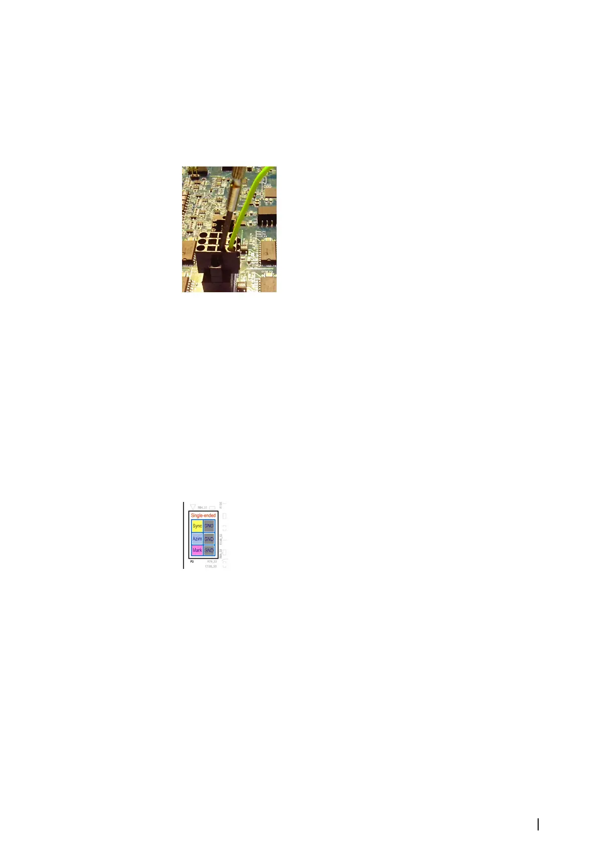
To insert a wire to the connector, use a small screwdriver. Insert a flat-blade screwdriver in
the rectangular hole of the connector and then put the wire in the corresponding round
hole. Then remove the screwdriver and the wire will be fixed.
The following sections describe the different connections.
Single-ended synchronization signals
There are two ways to connect single-ended lines to the MK 6.0 Radar Interface box. They can
be connected using a special connector for single-ended signals or using differential
connectors. There are special conditions and limitations for single-ended connections using
differential connectors.
Single-ended connection using the single-ended connector
The connector has the following pins:
• Sync
• Azimuth
• Mark
• 3 GND pins
The single-ended connection using the single-ended connector.
The following color coding is used for wires:
• Grey - Ground (GND)
• Yellow - Sync
• Blue - Azimuth
• Magenta - Mark
All the GND pins of the single-ended connector are connected with each other and the
video GND on the board. In most cases it is correct and sufficient because the grounds are
also connected on the radar side. If grounds should not be combined, it is possible to use
differential connectors (see "Single-ended connection using the differential connectors" on page 12 for
details). Single-ended inputs have a range of +/-20V. The triggering level can be set within
these limits. The synchronization pulses can be displayed using the MK 6.0 Radar Interface
box oscilloscope.
Connections | MK 6.0 Installation Manual
11