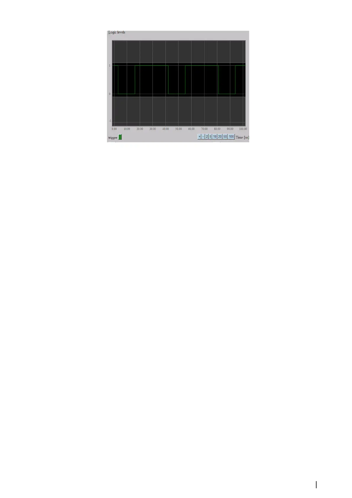
Litton/Sperry sends several bytes of information and this picture shows only the first one but
it can still be useful to check polarity of the signal and figure out if the MK 6.0 Radar Interface
box receives anything at all.
Like other differential inputs, AL is equipped with a 100 Ohm resistor which can be used for
impedance matching. Selecting the “100 Ohm dif. imp.” check box connects the 100 Ohm
resistor to the input.
Radom synchronization signals
Radom uses differential synchronization signals so everything which is described in "Differential
synchronization signals" on page 24 is applicable for Radom with one exception. Radom does not
provide a separate Marker signal. Instead, one of the Azimuth signals per turn is long and it
indicates the start of a new scan. Radom usually generates 2048 Azimuth pulses per turn, so
it is difficult to notice the long one among many others on the oscilloscope.
Idle mode
When the “Stop” button is selected, the system is operating in the idle submode and it does
not acquire any signal. The board sends one empty sweep to the Extractor/Tracker per
second as the "still alive" message.
Automatic search for trigger levels
To simplify the settings of triggers levels for single ended and composite radars, the MK 6.0
Radar Interface box provides a function for automatic search of these levels. The “Find Sync
trigger level”, “Find Azimuth trigger level” and “Find Marker trigger level” buttons start the
procedure of automatic trigger level configuration. Before starting the procedure, switch the
radar transmission on, select the correct type of radar and check that the polarity of each
synchronization signal corresponds correctly. The procedure can take several minutes to
complete, it depends on the signal period. Because the Marker signal is sent by the radar only
once in 2- 3 seconds, the calculation of the Marker trigger level takes the longest time.
When the procedure is finished, it reports if it succeeded or not. The procedure can fail if the
signal is lost or if it is different from what is expected for the specified type of radar. When the
procedure finishes, the system automatically switches to “Sync”, “Azimuth” or “Marker”
submodes correspondingly, to show the result. Then the level of the trigger can be manually
corrected.
Settings of video signals
The following settings are applicable for the video signal:
“polarity” - if the radar provides a negative signal, it can be inverted by the board. To activate
inversion, select “Negative”.
“input range” - input video range parameter. By default, the MK 6.0 Radar Interface box uses a
maximum input video range of +/- 8V. It is important to use a sufficient input range. If the
input range is too high compared to the video signal, the ADC will not be used efficiently. If
the video range is too low, the video signal can be truncated. See the figure below.
Settings | MK 6.0 Installation Manual
25