“video range shift” - the shift of the output video range regarding input video range. It is
expected that radars provide video signals which are only positive or negative so the useful
part of the video signal uses only half of the ADC range. The Extractor/Tracker needs to have
positive video which starts from the bottom of the range. While sending the data to the
Extractor/Tracker, the MK 6.0 Radar Interface box converts them to the format, needed for the
Extractor/Tracker. This converter uses only half of the input video range. “Output range shift”
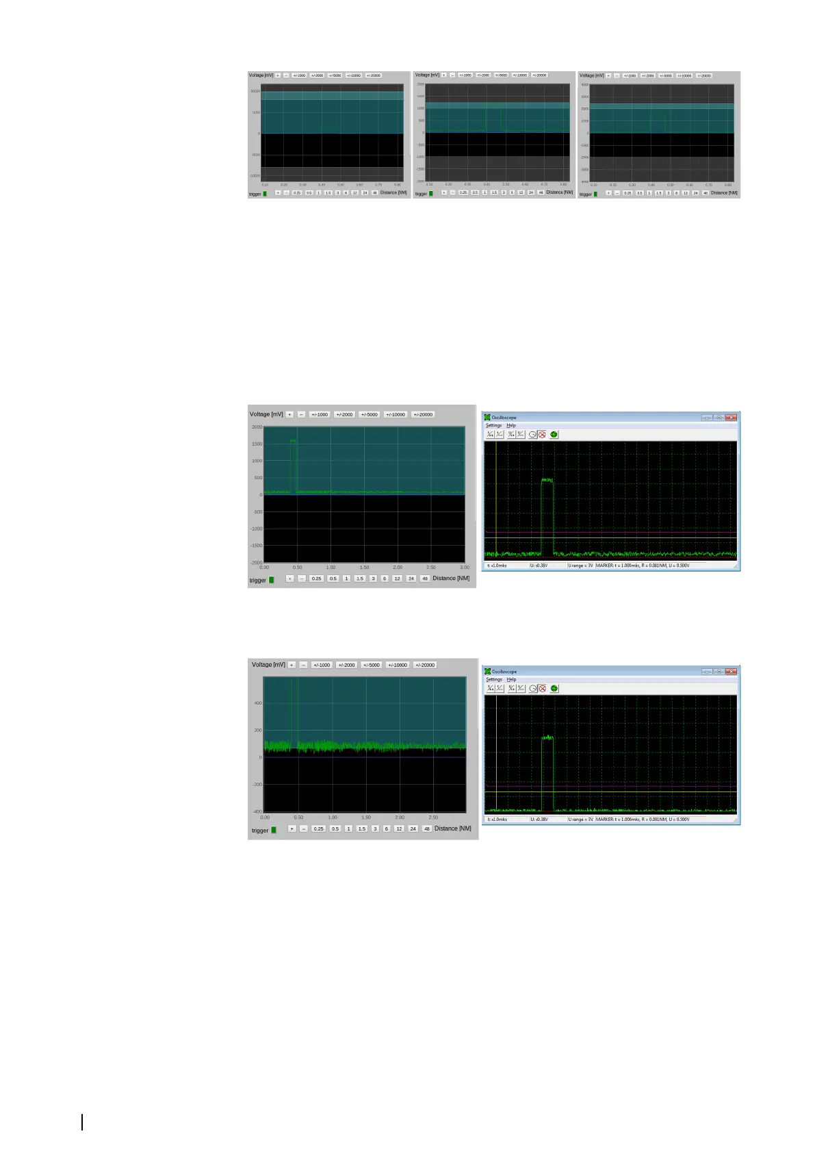
controls which part of the input range to use. The oscilloscope shows it in cyan.
By default, the shift is 0 and output video range is the upper half of the input range, see the
figure below. It shows that the signal does not sart from the bottom of the video range and
that high amplitudes are truncated. The signal can be seen on the Extractor/Tracker's
oscilloscope.
In the following figure, the video range is shifted up at 70 mVolts. The noise is on the bottom
of the output video range. The signal can also be seen on the Extractor/Tracker's
oscilloscope.
“sync delay” - the sync delay value is in nautical miles. Compensation of Sync Delay is
provided in the MK 6.0 Radar Interface box. The Sync Delay setting in the VarpPCI.ini file is
ignored by the Extractor/Tracker when it receives data from the MK 6.0 Radar Interface box.
Sync Delay is strongly positive. The bigger value of Sync Delay causes the bigger delay
between the synchronization event and the beginning of the sweep. When the “sync delay”
value increases, the signal in the oscilloscope diagram moves left (see the figure below) and
the targets on the radar video of the Extractor/Tracker application moves close to the center.
26
Settings | MK 6.0 Installation Manual