Connections
The following sections describe the general type of connections applicable to the MK 6.0
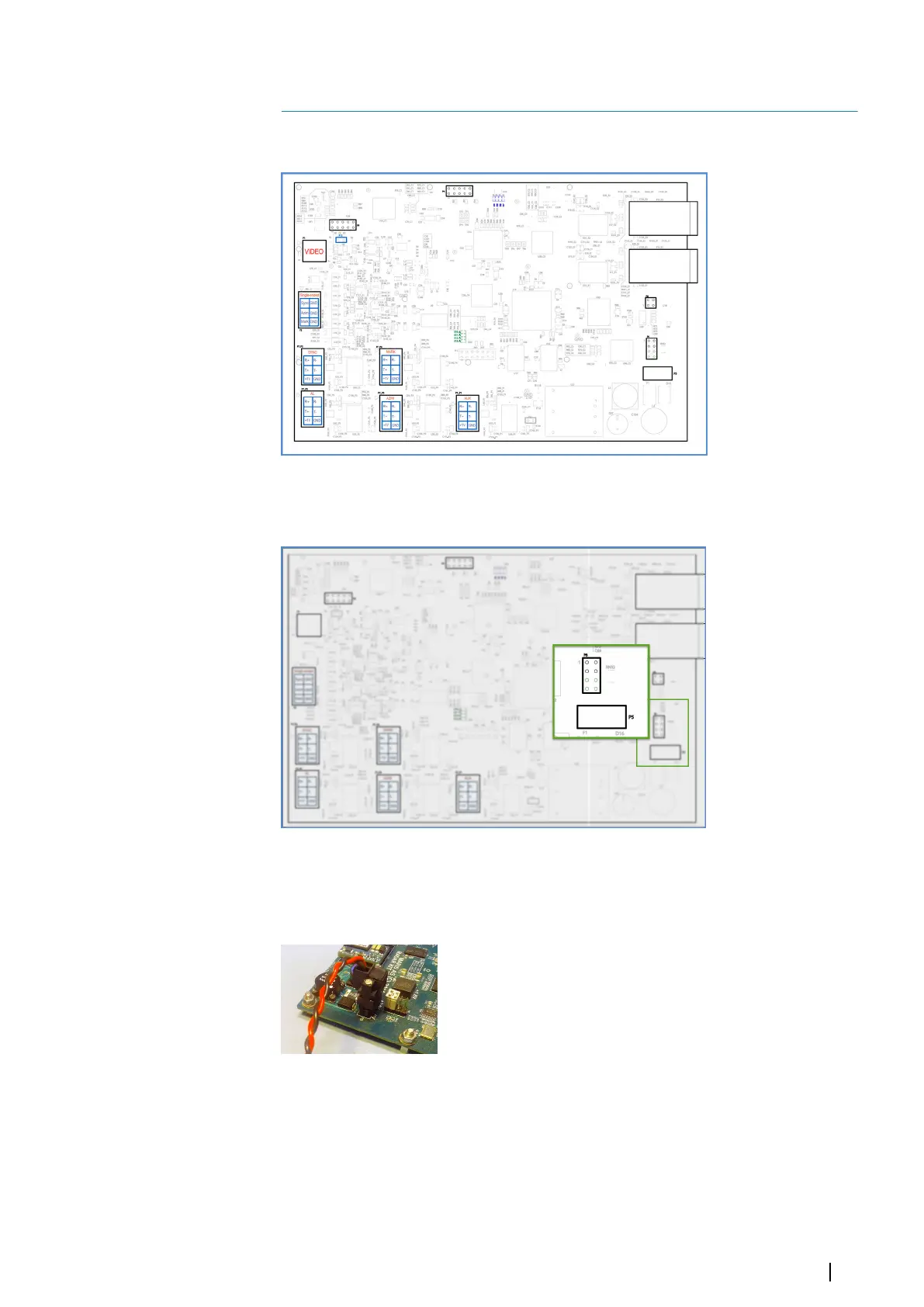
Radar Interface box board represented in the figure below.
The MK 6.0 Radar Interface box board. Items, used in the installation process are indicated.
Power
The power connector P5 and the jumper slot P6. The default jumper configuration is green .
Use the P5 connector to power.
Rated power is DC 24 V.
Power consumption is maximum 10 W.
Power connector on the MK 6.0 Radar Interface box board.
Indication of the status with LEDs
LEDs D10-D13 are located close to the MARK connector and indicate the status of the
system. They can be useful when the board is not able to communicate using the Ethernet.
3
Connections | MK 6.0 Installation Manual
7