indicator on the oscilloscope shows the synchronization status. Shift and sync delays are
ignored in this mode.
Sync, Azimuth, Marker or Alt states
When the “Sync”, “Azimuth”, “Marker” or “Alt” button at the top of the page is selected, the
system acquires signal from the Sync, Azimuth, Marker or Alt connector respectively. The
acquired signal is not sent to the Extractor/Tracker, it is only shown in the oscilloscope. These
submodes are used for visualizing the synchronization signals and setting the
synchronization parameters.
Synchronization signals are self synchronized. This means that if the Sync signal is shown in
the oscilloscope, the same Sync is used for synchronization. However, if the system cannot
acquire the signal within a certain time interval, the signal is acquired without
synchronization. This means that a random part of the signal will be displayed. The Sync/
async indicator on the oscilloscope shows if the signal was acquired synchronously or not.
The settings for the video signal (amplification, Sync delay, etc) are not applicable for
synchronization signals. The MK 6.0 Radar Interface box processes various types of
synchronization signals differently but some parameters are applicable for all synchronization
signals. The digital filter can be specified for each of the synchronization signals by means of
“digital filter” control. The filter can be used to remove high frequency noise on the line.
Applying this filters does not visibly affect synchronization signals on the oscilloscope. If the
synchronization signal has the polarity opposite to what is desired, it can be inverted using
“polarity” settings. These inputs are opt-isolated on the board. This means that if the cables
are connected with wrong polarity, the the PCB will not be damaged.
Single-ended Synchronization
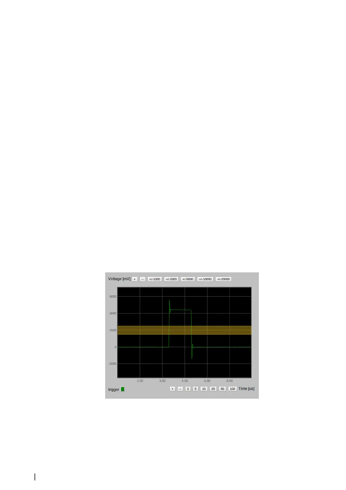
For all single ended signals the oscilloscope displays the triggering level (yellow line for Sync,
blue for Azimuth and Magenta for Marker) besides the signal trend. For stability of the
synchronization, the board uses hysteresis. The thickness of the line corresponds to the value
of the hysteresis. For single ended signals the hysteresis is the 1 V. In the figure below the
single ended Sync is shown.
In this state, the X axis is in microseconds and the Y axis is in millivolts. The range is +/-20 V.
The yellow line on the picture is the level of the sync trigger. To guarantee stable
synchronization the trigger must be fully inside the synchronization pulse, preferably in the
middle. The trigger level can be moved using the controls.
The trigger level
Single ended Azimuth and Marker look similar except for the trigger level color. Because the
Marker signal appears once per antenna turn, it is seldom redrawn. It also affects the
redrawing of the position of the trigger level, so be patient while working with Marker signal.
22
Settings | MK 6.0 Installation Manual